Steam Drifter – “Formidable”
In around 1977 I attended a weekend workshop seminar on the herring fishing industry in East Anglia. The course was held at Belstead House near Ipswich. One of the expert speakers was Ted Frost who talked at length on the building of a steam drifter. Ted was a shipwright by trade and served his apprenticeship at Chambers yard on Lake Lothing, Lowestoft. This yard built many wooden sailing and steam drifters and trawlers, and was responsible for the standard design of steam drifter built for the Navy during the war.

Ted had produced a very comprehensive set of magnificent pencil drawings illustrating every stage of the construction of steam drifter “Formidable” LT100 which was built in 1917. During his apprenticeship and later, Ted worked on every aspect of the building of these vessels. In 1985 his drawings and constructional descriptions were published by Terence Dalton in “From Tree to Sea”. I don’t believe that any of the wooden steam drifters have survived in preservation, so Ted’s book is an invaluable record of this bit of maritime history. In later years Ted went to sea as ship’s carpenter with Houlders, on their refrigerated meat boats on the South American run. Before retirement he served as Clerk of the Works for Lowestoft. A true gentleman, I was honoured to call him a friend, and I treasure my copy of “From Tree to Sea” signed by him. We will not see his like again.
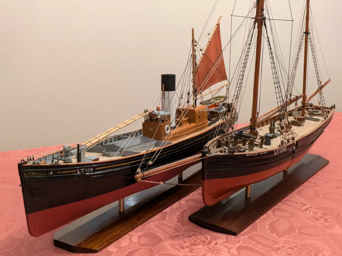
Having completed the build of “Warrior” I was looking for a new project. I didn’t fancy another ship with an extensive sailing rig, so “Formidable” beckoned. A year or two ago I completed the Lowestoft sailing trawler “Master Hand” to 1:48 scale, so I reckoned that she would be well complemented by a steam drifter from the same port, same era, at the same scale.
Although there is ample information in “From Tree to Sea” to construct the model, I acquired the commercial plans for “Formidable” , which are at 1:33 scale. I was able to scan, manipulate and print the body plan at 1:48 scale, and construction commenced.
I briefly contemplated building the model as a full constructional replica of the prototype vessel. The book “From Tree to Sea” gives ample details of every element of the construction, and it would be perfectly possible to recreate this construction in model form. But in reality, this project requires a larger scale; a minimum of 1:24, giving a model about 4ft in length. I didn’t want to construct this size of vessel, so opted for conventional plank-on-bulkhead model construction.


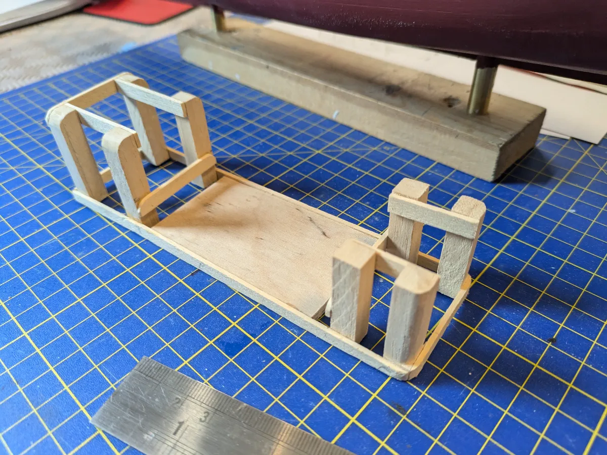
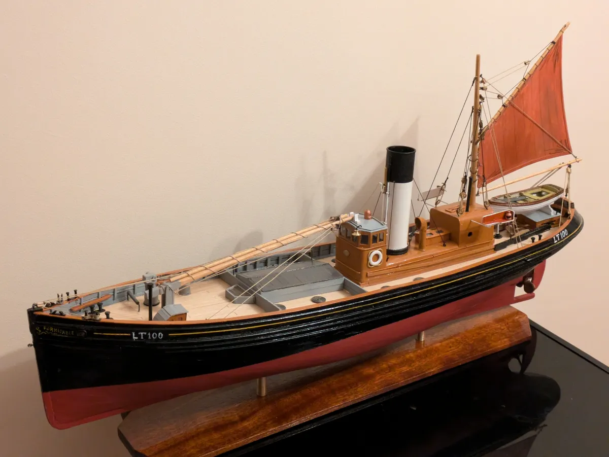
The model at 1:48 measures approx 23½” overall and 5″ beam. The model is to be a static display model, not intended for sailing the pond. The keel plate and bulkheads are formed from 4mm ply. Profiles were traced for the keel plate which was cut out in one piece. The upper edge of this corresponded with the deck line at the centre, while the lower edge was at keel level. Paper templates were traced and cut out from the body plan, transferred to the ply, and the bulkheads were cut out using a fretsaw. Slots are cut to fit the bulkheads to the keel.
In this model, the datum for the build is the keel line, with all bulkhead stations vertical to this. The actual designed waterline is not parallel to this. When afloat the vessel trims about 3ft “by the starn” as boiler and engine are located aft. She would gradually trim forward as she took on her catch of herring.
The keel plate is cut out and trimmed to shape taking great care to form the sheer line accurately. Slots are cut to take the bulkheads. At this stage we make the arrangements for mounting the hull on her baseboard. Regular readers of my constructional articles will be familiar with this, but the technique bears repetition.

Two brass keel pillars will support the hull. Positions are chosen equidistant from stem and stern, and vertical slots 4mm wide are cut into the keel plate. Care must be taken to ensure the slots are vertical to the design waterline, NOT parallel to the bulkheads. Two nuts about 10mm square are made from ⅛” thick brass scrap, drilled and tapped 4BA. These are inserted horizontally into slots formed in the keel plate about 20mm from the baseline. These intersect the vertical slots which will take the 4BA securing screws. The nuts must be a firm fit into the slots and are glued in position. There must be about 15mm of vertical slot above the nuts to accommodate the “tail” of the screws. I cut and glue two small support chocks under each brass nut, just for additional support. Brass pillars are turned and bored on the lathe, and parted off to length. The forward pillar must be longer than the after one to allow for the “rake” of the keel. The tops of the pillars are slotted to allow the keel to fit. I temporarily mount the hull at this stage on a scrap piece of 2″ x 1″ wood. This allows the hull to be mounted in the vice during the build.
The bulkheads are slotted to fit into the corresponding slots in the keel. It is important to take the time to accurately shape the bulkheads, especially the deck camber. All the bulkheads must sit at the correct height ensuring a uniform sweep of the deck in both camber and sheer. Toward the ends of the vessel the bulkheads are bevelled to allow a snug landing for the planking. Time spent at this stage pays dividends in achieving a “fair” shape to the hull.
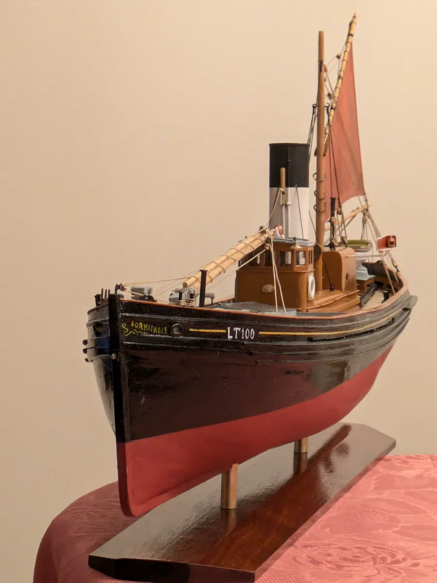
The most difficult part of the hull construction is the formation of the counter stern. This drifter features a reverse-counter. Ted Frost referred to this as a “tug stern”. Many drifters and trawlers were built with a conventional counter stern in which the stern bulwarks overhang above deck level. The drawback of this feature is that it is vulnerable to damage in a congested harbour. With the tug stern the bulwarks are protected from damage by the rubbing strake at deck level.
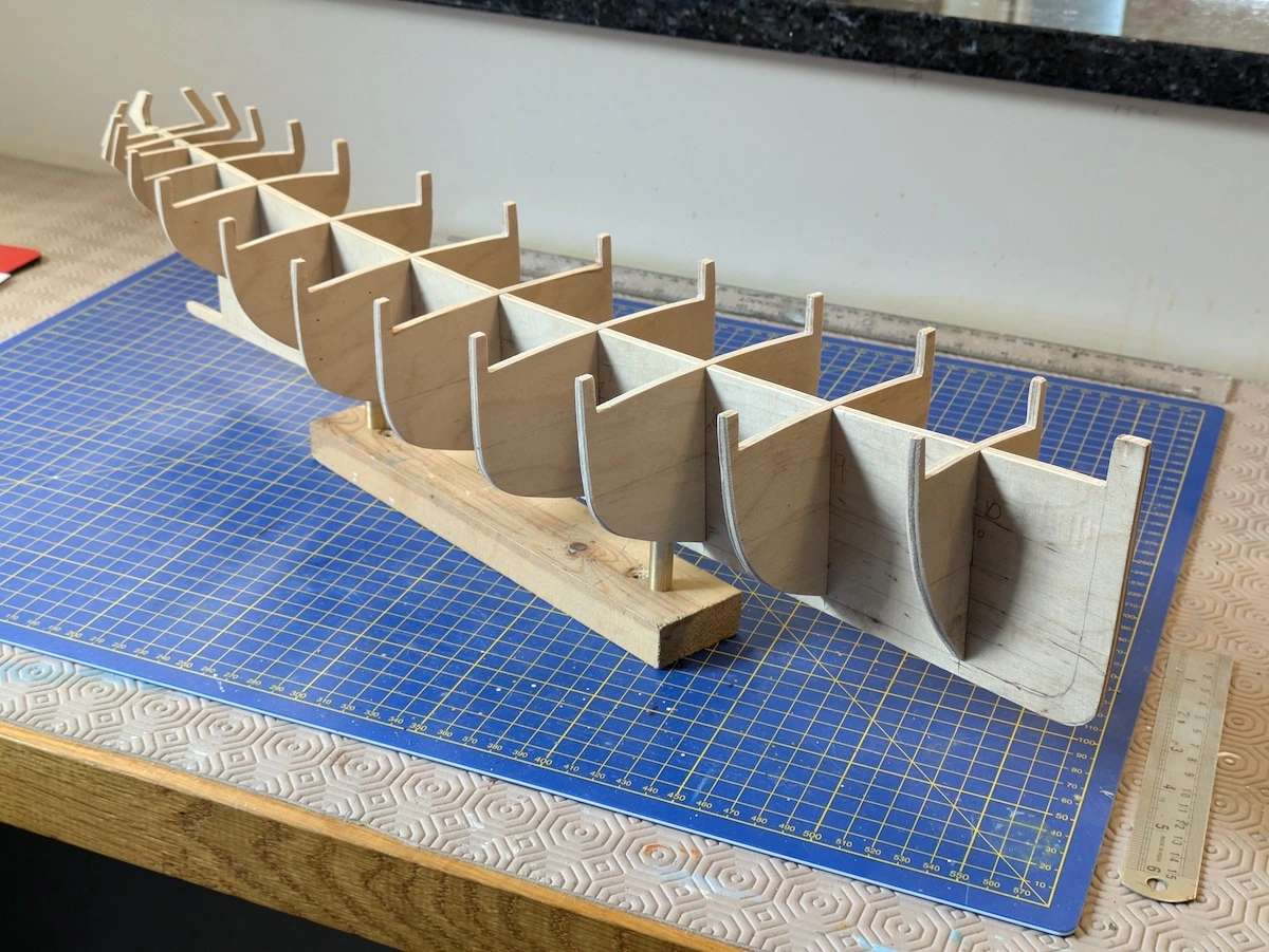
The counter (the portion of the hull abaft the sternpost) is formed on three bulkheads plus the aft end of the keel plate. All of the bulkheads have “ears” above deck level which will support the construction of the bulwarks. These must all be shaped with great care, accurately slotted and bevelled. The sheerline at the stern is very distinctive in this vessel, and it is important to get it right.
At this stage all the bulkheads are located and glued. A short section of deck substrate is formed from 1mm plasticard covering the aftermost five bulkheads. Accurately cut and filed to shape, this is carefully fitted and glued in position. This substrate will ultimately be planked over. A length of 2mm square limewood is steamed and carefully bent to the stern profile. This is glued to the outside of the stern at deck level, ensuring that it follows the correct sheer. This simulates the counter covering board in the real vessel.
At the forward end, a deck substrate of 1mm plasticard is fitted, covering the for’d three bulkheads to the stem. A narrow tapered limewood fillet is fitted on either side of the stem from deck level down to the keel. This is shaped with a varying bevel giving a secure place for fastening the forward ends of the hull planking.
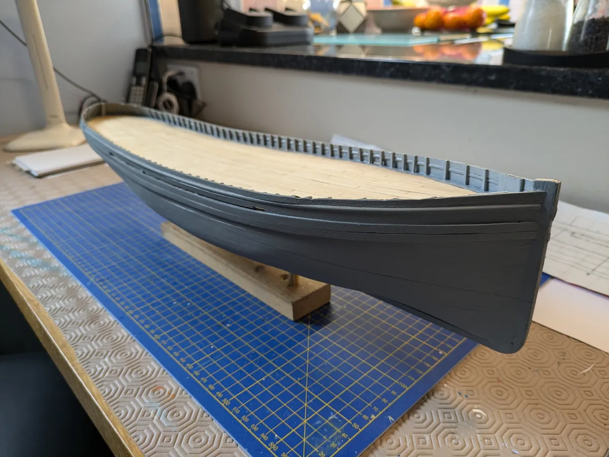
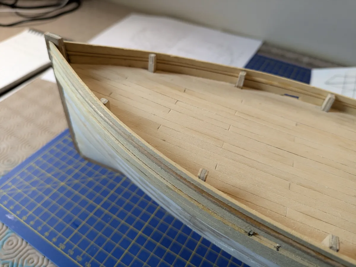
The hull planking commences with the sheerstrakes, or wales. These are fitted from deck level downwards. The upper two strakes are thicker than those below, and are tapered forward and aft. The aft ends must be carefully shaped and faired into the counter. This vessel has a pronounced sheer (‘sheer’ is the vertical curve of the deck line, sweeping gracefully upward toward the bow and stern). It is important that the sheerline looks “right”; an error here can ruin the appearance of the completed vessel.
To be continued...
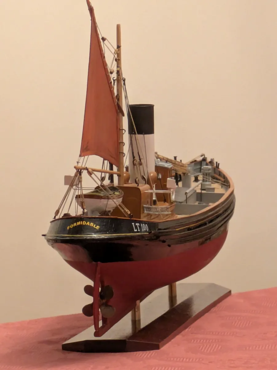
The planking is straightforward; I used 0.5mm by 5mm limewood strips, tapering and inserting stealers where necessary. All of my previous builds have been sailing vessels, but in “Formidable” I had to form a bossing for the propeller aperture. I actually forgot this until after the planking was complete, so had to add it as a bit of an afterthought.
Three half-round rubbing strakes are located on the thicker wales or sheerstrakes. These must follow the sheerline curve and be equidistantly spaced. Again, these are visually prominent, so care must be taken to ensure they look “right”.
We now need to plank the deck. A further substrate of plasticard is fitted in between the forward and after sections already in place. The deck substrate should now form a fair surface showing the correct sheer and camber. The deck is planked with 0.5mm x 5mm limewood cut into 4″ lengths. The kingplank is laid first, taking great care to get it straight and dead central.

I’ve used a shift of butts pattern repeating every three strakes; each butt is shifted 1.33″ from its neighbours . Care must be taken to ensure that every third butt are lined up athwartships-wise. At this stage we omit the covering board (the outermost deck strake, following the curve of the deck-edge.
The next task is to build the bulwarks above the deck level. This job is done in two sections. The main bulwarks are conventional construction of fore-and-aft strips, while those at the stern are planked vertically. The shipwrights refer to these as the “starn palins”. In the model, this was quite a tricky job. We have four pairs of bulkhead “ears” plus the stern end of the keel plate on which to form the bulwark palins. I cut a cardboard template to fit round the complex curve of the tug stern.
This wasn’t easy. Several clothes-pegs and lots of patience, and several attempts before it looked right and fitted. I then planked over the template with 0.5mm x 5mm strip laid vertically, commencing on the centreline. Being careful to retain the horseshoe-curve of the template, I could then turn it over and similarly plank the inside surface of the “starn palins”. This formed quite a strong and rigid fitment, and once trimmed to shape fitted perfectly in place.
The main part of the bulwarks are planked more conventionally. A profile needs to be formed. In the prototype vessel, for appearance’ sake, the upper and lower bulwark strakes are flat, while the wider middle strake is domed on the outside face. It is important to get this looking “right”. A further complication is that for about two-thirds of their length amidships, the bulwarks are “floating”, i.e. not touching the deck. A gap of about 1″ is left in the prototype vessel to allow deck water to clear. Water trapped on deck represents a substantial loss of stability, so these “freeing ports are essential. The gap must not be greater than about 1” as the herring catch would wash overboard!
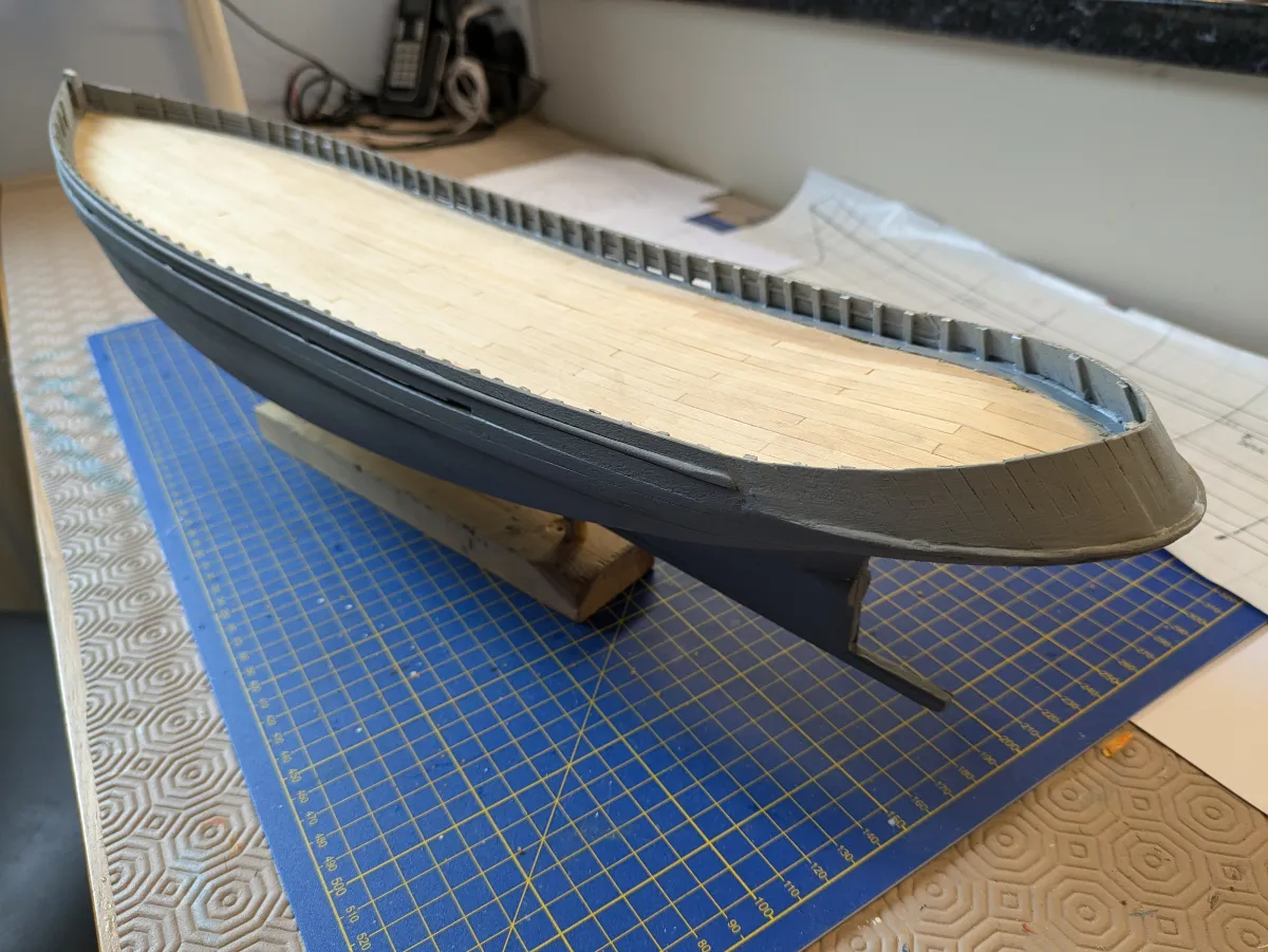
Fitting the bulwarks must be done with care. The supporting bulkhead “ears” will be removed, so must not be glued to the bulwark strakes. And said strakes cannot be secured to the deck as they “float” as described above. In an earlier build, I constructed the bulwarks as a double-thickness skin, but here I just formed a single thickness. Once in place the bulkhead ears are removed, filed flat to the deck, and the outer strake of the deck (the covering board) fitted. The deck can be sanded down and given a couple of coats of satin varnish. Once dry, the covering board is masked off with tape, and the inside of the bulwarks painted. A row of bulwark stanchions are fitted, referring to the drawings for position and spacing, then a further coat of paint (satin light grey) applied.
The bulwark cap rail is now fitted. Constructed from 1.0 mm x 6mm limewood, it is fitted in several sections shaped to accommodate the curve of the bulwark. The cap rail covers the top edge of the bulwark, and the upper ends of the bulwark stanchions.
A number of pin rails are made and fitted in place on the inside faces of the bulwarks. They are curved to match the longitudinal curvature of the bulwark, and notched to fit neatly around the bulwark stanchions. A more difficult task is the Cavil rail. This is fitted on the inside face of the bulwark stern palins, curving around the stern port to starboard. I made a card template to get the shape correct. The cavil was formed from 3mm ply, cut to the template then bevelled to match the tumblehome of the palins. Quite a bit of fiddle, trial and error here, but eventually fitted in place.
We can now paint the hull exterior. Matt dark red below the waterline and satin black above, masking off to provide a clean crisp waterline. The cap rail is painted dark brown.
That is the hull essentially complete, and she’s beginning to look right smart!
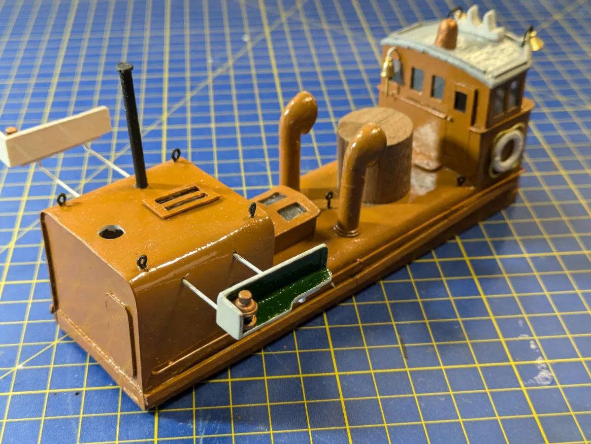
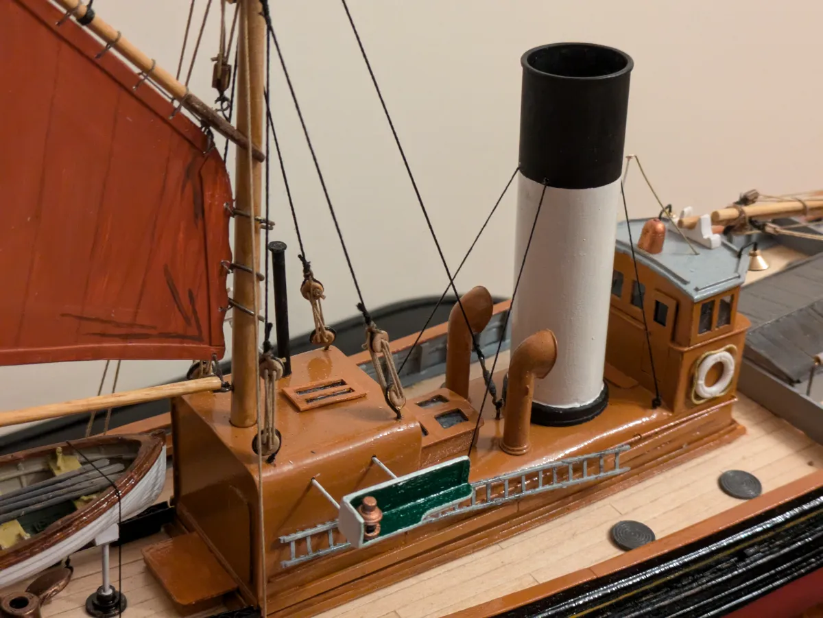
The next task is the construction of the deckhouse. This comprises the engineroom casing, with the wheelhouse mounted atop at the forward end, and the galley integral at the after end. Quite a complicated structure, with the upper edges of the galley and casing radiused. Also the forward corners of the structure are radiused. I built a framework of limewood section and strip which initially was quite flimsy and flexible. As extra components were added the structure gained strength and rigidity. The lower edges of the deckhouse had to be shaped to match the sheer and camber of the deck. Once the framework of the deckhouse was complete, thin plasticard was cut and formed into the engineroom casing. The galley was next, finally the base of the wheelhouse. Having completed this bit of construction, I discovered that the whole unit had warped slightly, and wobbled when located into position on deck. A bit of trimming of diagonally opposite lower surfaces ensured a snug fit. 3mm plastruct angle was cut and formed accurately into a coaming into which the deckhouse would be a tight fit. The complete coaming unit was painted then glued in position on the deck. The deckhouse is not fitted at this stage, as a lot more work is required to finish it off.
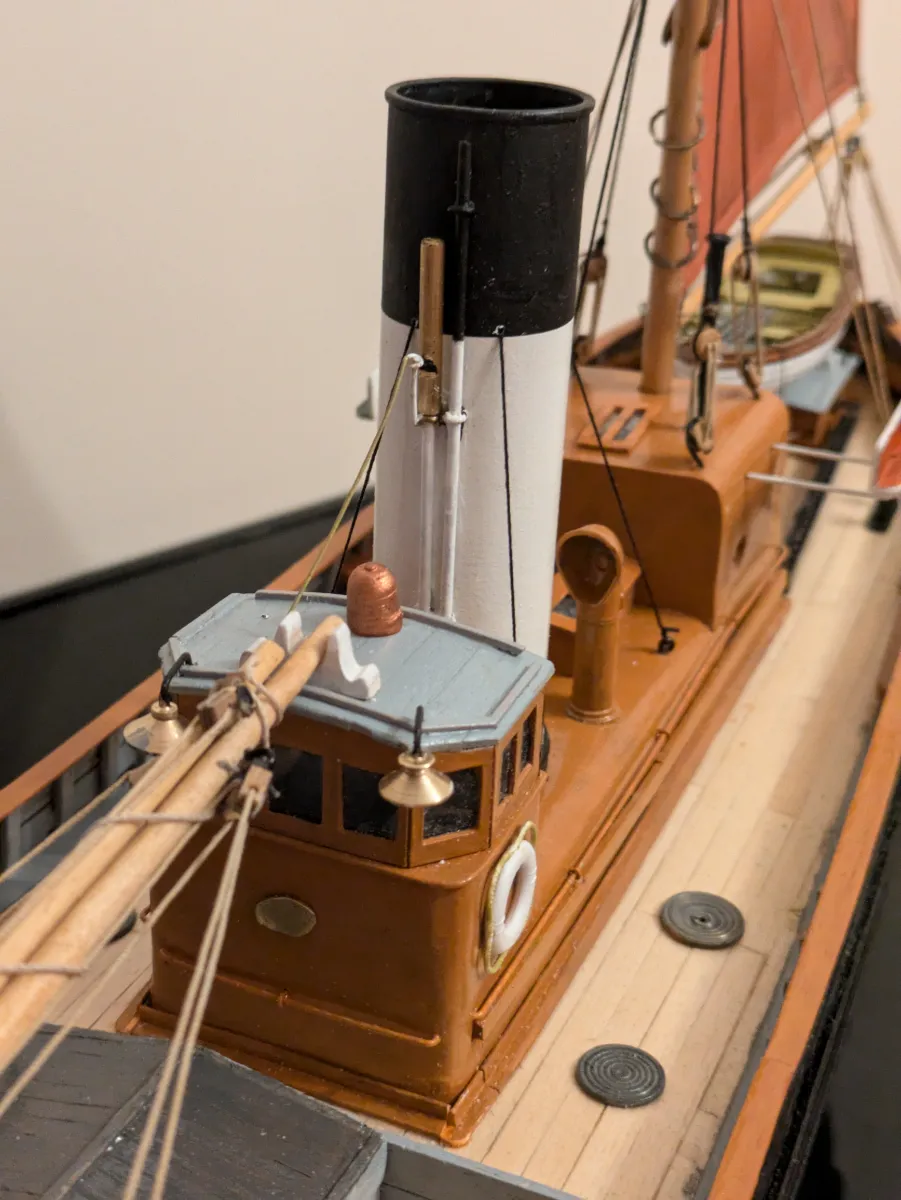
The wheelhouse needs to be completed by adding windows and roof. The windows are formed from thin plasticard, cut accurately into a strip and carefully scored with a knife to allow folding at the correct angles to form the front and sides of the wheelhouse. The window apertures are cut. The whole inside of the wheelhouse and window frames are painted matt black, as the inside structure does not match the prototype. The matt black renders the internal detail invisible. The windows are “glazed” using clear plastic sheet glued to the inside. I made a mistake here. Having completed the wheelhouse, I realised that there was no way to get in! I then had to cut a doorway in the aft wheelhouse bulkhead, and fit a door. Glazed to match the other wheelhouse windows, the final touch was to drill 1mm and insert a tiny piece of brass wire to form a doorknob! The wheelhouse roof was planked and fitted with rain strips. A tiny section of dowel formed the magnetic compass, painted copper. In the prototype the compass was visible at the wheel by means of a periscope arrangement. The “Mitch board” was made and fitted. This is a decorative crutch fitted at the fore end of the wheelhouse roof, supporting the lowered foremast when fishing. I’ve often wondered if this fitting was named after an interpid fisherman called Mitch!
Much further detail to be completed on the deckhouse. Engineroom skylight and ventilators. Galley door. Funnel. Sidelights. The latter are bracketed off the galley house. Painted red (port) and green (starboard) I must admit to actually getting the colours on the wrong sides! I mean….I’m a Master Mariner! This error is something I’m keeping very quiet about! The light boards were rapidly repainted in the correct colours!
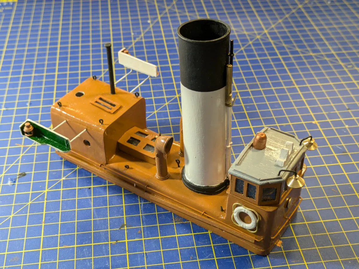
The funnel was originally a Steradent tube! Exactly the correct diameter, but took considerable sanding before painting to ensure the instructions weren’t still readable. Cut to length, the bottom edge was filed to give the correct rake of the funnel. The steradent tube cap was repurposed to form the funnel base, where it was mated to the engine-room casing. This base and the funnel top were painted black, the main part of the funnel white. Brass wire and rod of different diameters was used to form the steam pipe and whistle. Once fitted four funnel stays are rigged. A brass bell is fitted to the aft face of the wheelhouse, and two brass lamps to the forward corners.
Drifters always carried a ladder. Often, especially at low water, the quayside was considerably higher than the deck. The ladder was lashed to the boiler casing rails on the starboard side. Some time ago I built a shipyard diorama (the “Dandy Score yard”) which included a row of terraced houses. To provide a wooden paling fence between the shipyard and the house, I used some plastic fencing intended for scenic effects in 00 scale model railways. I took a length of this plastic fencing and removed every other paling. This formed a very acceptable ladder.
The mizzen mast is made, tapered and varnished, then fitted with a small wire pin in the heel. A hole is formed in the galley roof to take the mast, and a small hole drilled in the deck beneath to take the heel pin. Important to get the position of this hole correct such as the mast locates vertical athwartships with a small forward rake. Eyebolts are located in the galley roof to accommodate the mizzen mast stays.
We must now construct the steering gear. The vessel has a rod-and-chain system connecting the wheel to the rudder yoke. Wooden strips are attached to the sides of the engine-room casing to simulate the tubes carrying the rods. A deck box is constructed to take the rudder yoke, the arms of which protrude port and starboard. The upper surface of this box is planked, then fitted with the after cradle chock for the small boat.
The ends of the yoke are connected to the system by chains which run in channel section. These are made and fitted, the aft ends of the chain connected to the yoke arms. The forward ends of the channels butt up against the galley bulkhead corresponding with the tubes carrying the “rods”. In the model there is no connection between the yoke and the rudder, indeed the rudder hasn’t been fitted yet.

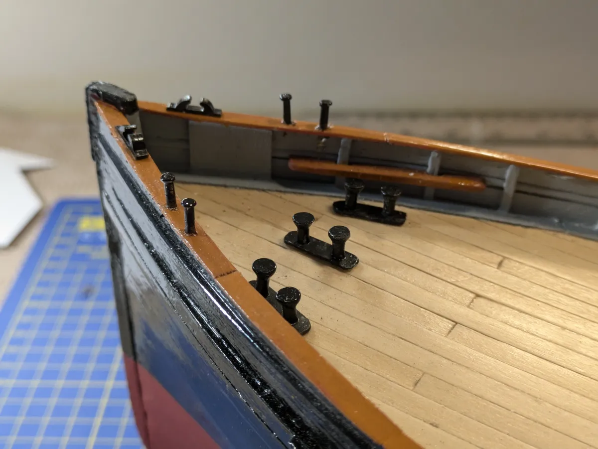
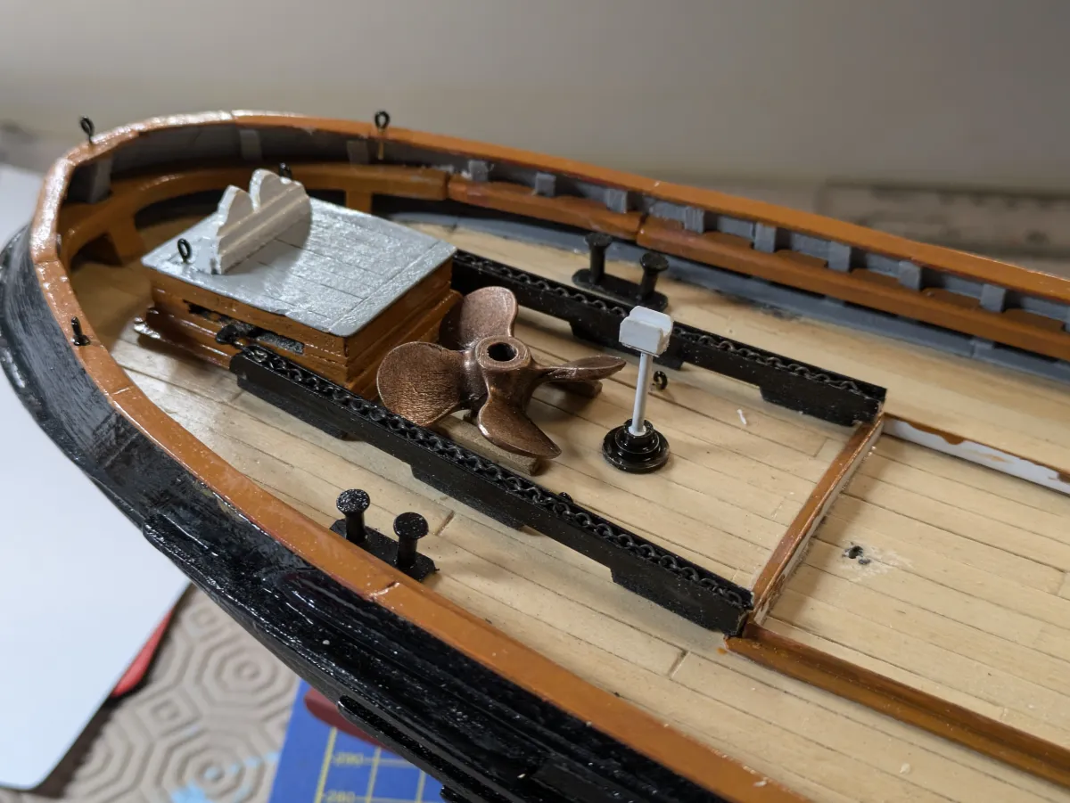
The forward end of the small boat will be supported on a pivoting chock mounted on a post on the deck just abaft the galley bulkhead. This is made, painted and fitted, as is the spare propeller mounted on bearers on deck. A few eyebolts are fitted to the deck to take the mizzen boom guys and the small boat gripes. A set of mooring bitts (double bollards) are made and painted. Two are fitted at the stern and five at the bow; three on deck and two on the bulwark rail.
The rudder is constructed from thin plasticard, planked on either side. Glued to the rudder stock (2mm brass rod) a number of gudgeon straps are fitted. Before assembly, the rudder stock is reduced to 1mm for a few millimetres at the bottom end, locating into a small hole drilled into the keel sole piece. The rudder and stock are purely visual, and not connected to the above-deck yoke. A 40mm propeller is fitted, again purely decorative, non-rotating.
The small boat is a Quaycraft resin moulding of a 14 foot workboat of the type carried by fishing vessels. These are beautiful mouldings, fully detailed. All that is necessary is to do a very careful paint job then secure in place in the chocks, making sure she is upright and level fore-and-aft.
The mizzen mast is now rigged with forestay and four shrouds set up on deadeyes and lanyards. Before this, three mast hoops are made from brass wire and painted. Dropped onto the mast before rigging the forestay and shrouds, these will be laced to the luff (leading edge) of the sail. A gaff is made and fitted with jaws to sit against the mast. Gaff boom and mast are stained and varnished, then fitted with the variety of brass eyes to take the running rigging. Peak and throat halyards, topping lift, sheet and boom guys are all rigged. The sail was made from thin plasticard cut to shape with the edges (luff, head, leech and foot) reinforced by thin plasticard strips. Holes were drilled in the head to take the throat and peak earings and the head lacing. Three holes were drilled in the luff to allow lacing to the mast hoops.
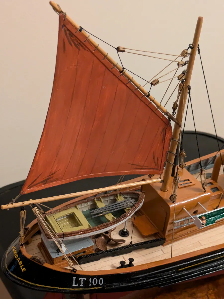
The sail is painted with acrylics. Basically a rich tan colour, smudges of black and ochre are added giving the sail a typical weathered appearance. The sail is “fitted” by earings at the peak, throat and tack (the lower forward corner) with an outhaul at the end of the boom. The sail is laced to the gaff along it’s upper edge; the lower edge of the sail is not laced to the boom, being “loose footed”. Finally, the three mast hoops are laced to the leading edge (the “luff”). This was all quite a fiddly job, but looked good once secured in place.
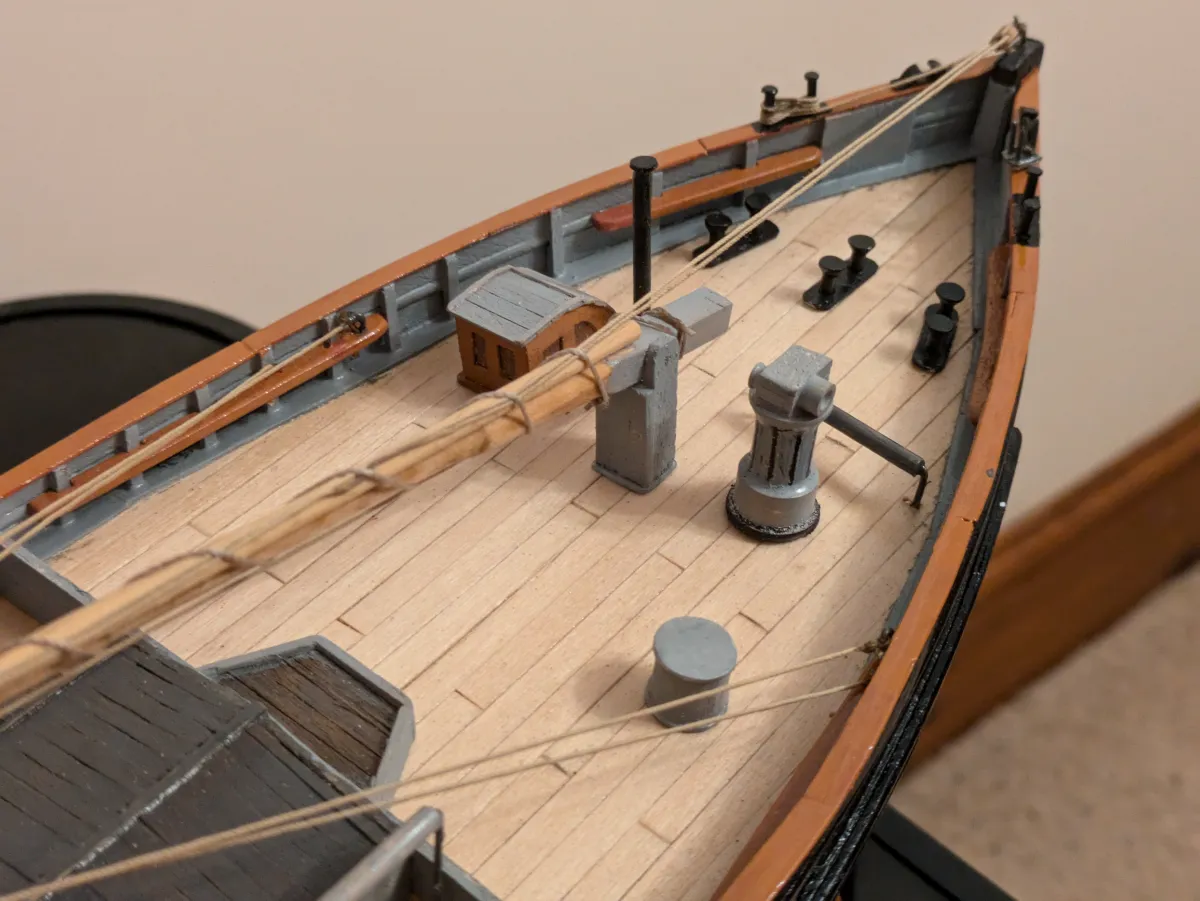
A variety of fittings made or sourced from my scrap box. I’ve been building ship models for over 50 years off and on, and my scrap box has a great collection of “left-overs”. Bollards, cleats etc. The hatch and kit boards are made and fitted, with a horizontal net roller fitted over the starboard coaming. Drift net fishermen always “cast their nets on the right side of the boat” as instructed in the Bible!
A model was constructed of the Elliott and Garrood steam capstan and fitted to the foredeck. This was a brilliant piece of equipment, made in their thousands at the Beccles works. Steam from the boiler passed from underdeck up through the middle of the capstan. A two-cylinder steam engine on top drove the barrel by means of a bevel gear and crown wheel. The capstan was immensely powerful considering the size of the engine components and was used for many functions; hauling the net warp, lifting the baskets of herring onto the quayside using the foremast derrick, and,most importantly, hauling the ship up to the quay. During the herring season (October/November in Lowestoft and Great Yarmouth) there may be several hundred drifters all vying to land their catches. With the boats mooring bows on to the quay, it was often necessary to force a boat in, squeezing between two moored boats. With a rope onto a bollard ashore and the engine on full power, the boat forces her way up to the quay.
Elliott and Garrood also built the boiler and engine for many drifters and trawlers locally. They developed the ingenious “monkey triple” steam engine especially for drifters. This was a very efficient triple-expansion engine. In a conventional triple expansion engine, the three cylinders are in-line. But with the monkey triple the HP cylinder is mounted atop the IP cylinder, sharing a common piston rod. The LP cylinder was adjacent. This made the engine shorter in length, and the engine-room could be a bit smaller. The crew cabin immediately abaft was thus a bit bigger.
The capstan was turned up from brass on the lathe and fitted with representative upper casing and small warping drum end on the top. Once painted, it was fitted to the foredeck making sure it was vertical to the waterline; the deck itself has considerable sheer and camber at this point.
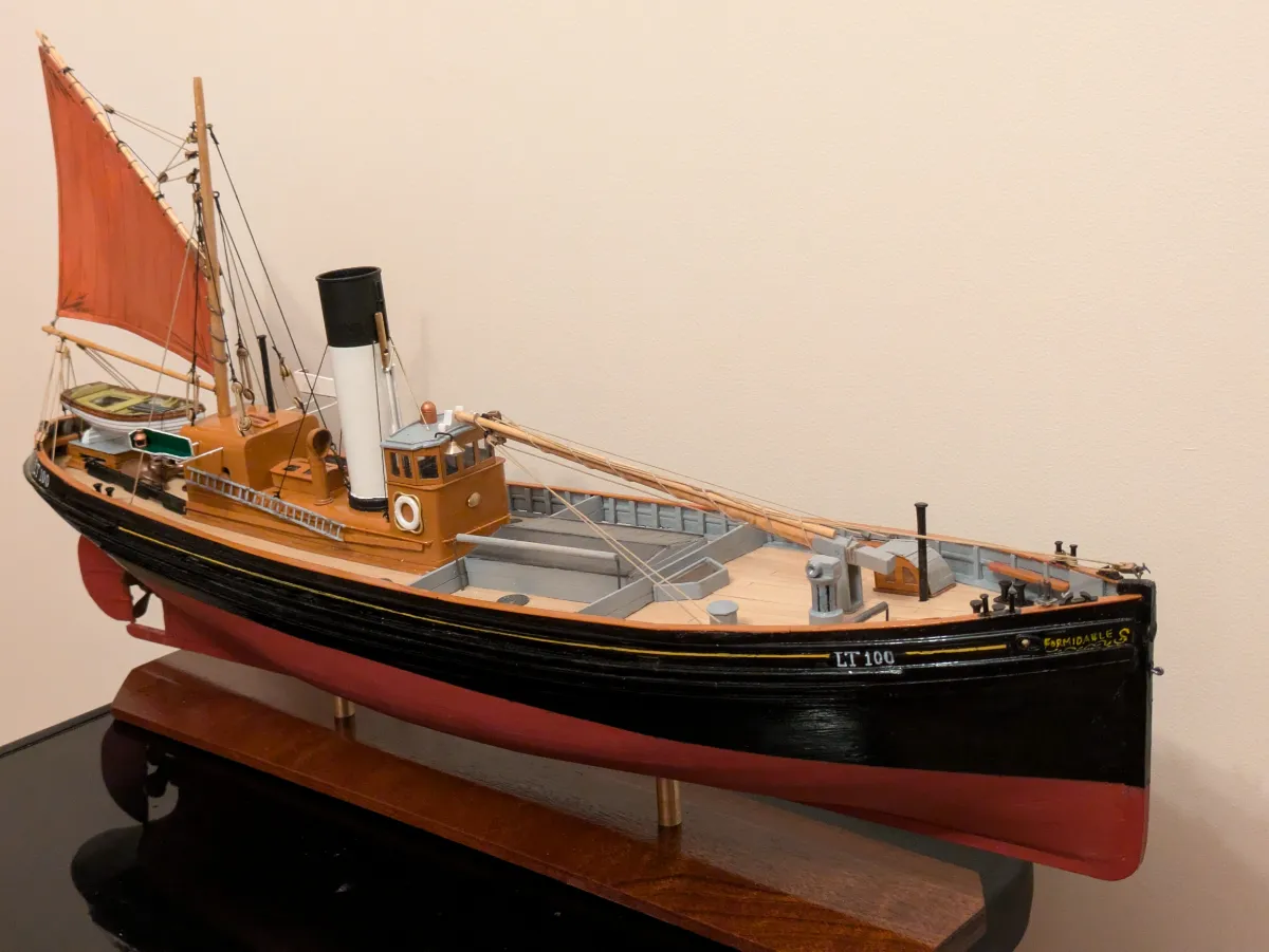
The fo’csle companionway is made, painted and fitted, as is the tabernacle for the foremast. The foremast and it’s derrick are made, stained and varnished, and fitted with eyes and bands for the rigging. Fitting and rigging is straightforward. We show the mast lowered onto the mitchboard atop the wheelhouse. Often, the mast was only raised when it is needed in port for discharging the catch.
The model is finished off by painting a very narrow gold line along the bulwarks, and giving her name and fishing number (LT 100). She makes a fitting companion to the sailing trawler “Master Hand” completed two years ago, and the Yarmouth lugger “Gypsy Queen” built by myself in 1977.
Incidentally, although the “Formidable” steam drifter represents future technology, while the sailing smack “Master Hand” the past, in fact “Formidable” was built in 1917, while “Master Hand” was built in 1920.
For the crews, drift fishing was grindingly hard work. Fraught with danger, conditions of work would not be deemed acceptable today. Pay was often uncertain. Fishermen were paid by the share of the catch returns. It may happen that a haul delivers a huge catch of the “silver darlings” taking maybe twelve hours to haul. But every other drifter in the area has had a bumper catch also, and all arrive at the fish dock at the same time. The glut of herring meant that price was low, and the crew payoff also.
No wooden-hulled steam drifter has survived into preservation. The last one was the Yarmouth boat “Wydale”. I remember seeing her leaving the harbour at Yarmouth on the 29th October 1961, heading for the scrapyard in the Netherlands.
The huge industry that was herring fishing is now but a memory. Herring stocks are miniscule compared to the multitudes that fed the world very cheaply prior to the First War. Nevertheless, longshore-caught herring and often found in the fishmongers locally during October and November, and there is nothing I like more than a brace of fried herring, fresh crusty bread and a big cup of tea!

Full Gallery
Click an image to see the full size images.