HMS “Warrior”
I received a new project in the winter of 2023.
Model Boats magazine has asked me to do a kit review of the Billings (Denmark) kit of HMS “Warrior”, the first ironclad built 1860.
It’s a large kit and took me several months. Every stage of the construction was photgraphed and copy written for articles for Model Boats.
As the project was rather large and there’s a lot of detail, it is divided into 3 parts.
Part One
Although the Napoleonic wars ended in 1815, there remained a significant distrust of the French. At the time, naval vessels were traditional “wooden walls”; wooden-hulled sailing vessels armed with batteries of cannon firing round-shot. But from about 1850 an arms race was triggered by the introduction of new technology. Steam propulsion was beginning to make it’s presence felt, and experiments were being conducted on the effectiveness of armour-plate against incoming shot. New guns were being developed which fired explosive shells instead of round-shot.
In 1859 the French warship “Gloire” entered service, marking a revolution in maritime warfare technology. This vessel, designed by Dupoy de Lôme, was converted from a traditional wooden-hulled warship, cut down by one deck and equipped with extensive armour plating protecting the wooden hull and her machinery. She was steam powered with engines developing around 1,500 HP giving her around 11 knots.
Although “Gloire” was the first armoured vessel, she was essentially a wooden-hulled warship. In Britain the Royal Navy was building a much more revolutionary and effective response. HMS “Warrior” would be the first iron-hulled fully armoured steam powered warship, and when introduced she would be the most powerful warship afloat. Designed by Isaac Watts, Chief Constructor to the Navy, “Warrior” represented a move into a new generation of warship development and construction.
Three elements were utilised in this vessel; iron hull construction, steam power to a screw propeller, and armour plating. The vessel was built by the Thames Ironwork Company and launched in December 1860. The contract price was £190,225. The steam machinery was contracted separately to John Penn & Sons of Greenwich for the sum of £74,409. Cost overruns resulted in a significantly higher price of the completed vessel to the Admiralty.

HMS Warrior kit 

“Warrior” was rigged as a three-masted fully-rigged ship, but her main propulsion was by steam power. Steam was provided from ten tank boilers to a twin-cylinder trunk engine of 5,772 ihp. This gave her a speed of 14 knots under power alone. The engines and boilers were all located below the waterline, as was the lifting propeller. Some earlier wooden-hulled steam warships were propelled by paddles, but these were vulnerable to battle damage.
Armament consisted of ten Armstrong 110 pounders, rifled and breech loading, firing 7″ shells to a range of around 3,800 yards. Additionally 26 muzzle-loading Armstrong 68-pounders and four 40-pounders were installed. All the guns were able to fire solid shot or explosive shells. Her armour plating consisted of 4½” hammered tongue-and-groove wrought iron plate backed by 18″ of teak hardwood. The armoured section of the vessel covered the midship 213ft of the ship, extending 16 feet above the waterline and 6 feet below. This armour was mounted onto the conventional iron structure of the hull.
“Warrior” is 418 feet overall length, 380 feet on the waterline. Her beam is 58 feet while her draught is 26 ‘ 4″ forward, 26’ 10″ aft. She displaces 9 ,210 tons. She carried 705 crew. She carried the designation “Armoured Frigate”, but was more powerful than any vessel afloat at the time of her introduction.
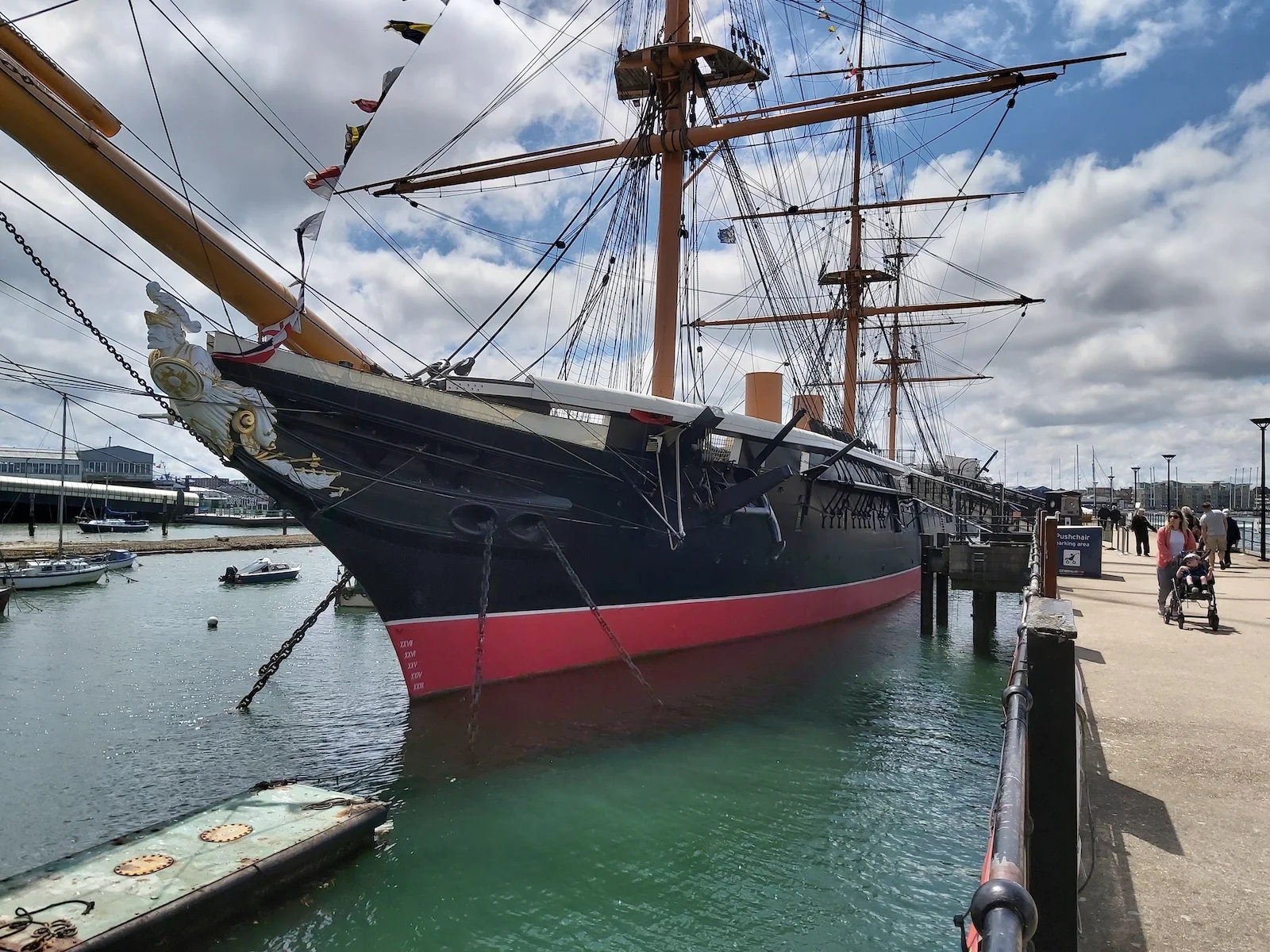
“Warrior” entered service with the Channel Squadron on 1st August 1861 under the command of Captain the Honourable Arthur Cochrane. She was based at Portsmouth for the whole of her commissioned service, and, indeed, is located there today, restored to her original condition.
Sea trials lasted over a year with many modifications made. Not surprising, considering she was the first of a new and very different class of vessel to that which the majority of the RN was familiar with! During her first commission she was visited by Royalty, British and foreign diplomats and many senior RN personages. She visited Cork, Lisbon and Gibraltar, escorting Queen Alexandra to her wedding with the Prince of Wales.
One of her officers was John Arbuthnot Fisher, gunnery officer and later to become First Sea Lord. Decommissioned in 1864 she underwent a refit at Portsmouth during which her armaments were strengthened. During her second commission under Captain Henry Boys one of her more unusual tasks was to tow a floating dock to Bermuda. Very few drydocks existed capable of stemming a vessel of “Warrior”s size. By 1875, “Warrior” had been overtaken by more modern technology, and was placed on the reserve list. She was paid off for the last time in May 1883. She then became a stores “hulk” at Portsmouth. Various auxiliary duties ensued, until 1929 when she was taken to Pembroke dock in Milford haven to act as a floating jetty for the Admiralty Fuel depôt.
She was now known as Hulk C77 and remained there until 1979 when her ownership was transferred to the Ship Preservation Trust and she was moved to Hartlepool. Her restoration was a lengthy process with much research carried out to allow her to be restored to her original condition. The restoration was an epic undertaking involving many organisations and individuals, too many to detail here. She finally arrived at Portsmouth on 15th June 1987, taking up the berth she occupies today. Open to the public she is a superb example of this iconic type of vessel, bridging the wooden wall sailing ships with todays modern warships.
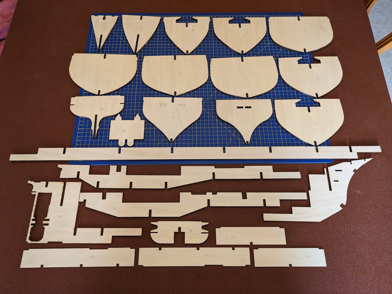
The Billings kit for “Warrior” comes in a large box, as befits such a large model. As is always the case with Billings kits, the box art is attractive, and the contents are well packaged. The drawings and instructions are comprehensive and well laid-out. Several languages are catered for. A complete numbered list of all components is provided, each component referenced to the particular ply sheet. The ply sheets are illustrated and themselves numbered. All construction stages are illustrated but not described in the form of text. This kit is described as at “expert” level, and I would concur with that.
The vessel is depicted at a scale of 1:100 giving an overall length of around 59″ or 1.47m. Construction i single-skin plank-on-frame built onto keel, deck and bulkhead elements from high-grade ply. All plywood elements are crisply and accurately laser-cut and it is a simple matter to carefully separate them from the ply sheets, afterwards trimming and cleaning edges with a file or rasp. I find it useful to number each element of the with pencil, identifying each from the drawings, before separation from the ply sheet. This obviates the possibility of locating a bulkhead, for example, into the wrong keel slot.
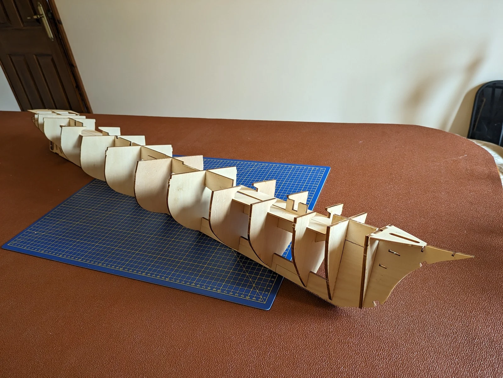
Assembly of the framework of the vessel is best done using a flat plank some 1.0 – 1.25m in length. This is not part of the kit; it is essential that this board is flat and straight. Once construction is underway, this board may act as a useful temporary mounting for the model.
Assembly of the hull framework elements was straightforward. All the bulkheads, keel, deck stringers, stempost, sternpost and other ancillary items were carefully separated from the ply sheets and cleaned up. The bulkheads for the bow and stern sections were roughly bevelled, then the units were assembled. All the laser-cut elements fitted together with great precision, enabling a tight and fair fit. Once assembly was complete, further bevelling was carried out on the bulkheads to ensure a fair landing for planking.
It was now possible to see the size and scale of this build. This is a big project! Easily the biggest I’ve tackled.
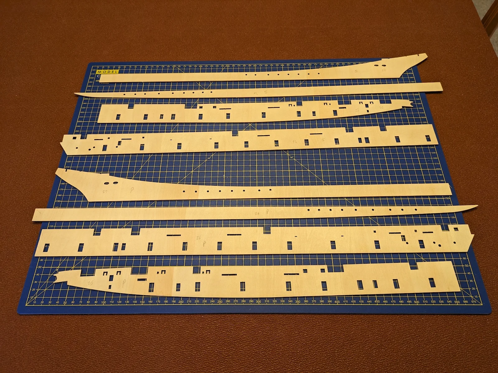
The next step was to fit the deck substrate. This is the 2mm sheet ply base upon which the deck planking will be laid. The ply deck is fitted in four sections, again, very accurate laser-cut forms. It must also be said that all the plywood from which the pre-cut components are formed is of very high quality. The deck was glued into position. I was now contemplating the most difficult part of the hull construction; the fitting of the topsides. These are the sides of the hull from the waterline up to the top of the bulwark rails. Laser-cut sections were provided in 2mm ply, eight sections in all. Exquisitely and accurately shaped, these components were carefully separated from the ply sheets and prepared for fitting. Many apertures and cut-outs were pre-formed but needed to be cleaned up prior to fitting. The topside panels need to be steamed in places in order to fit the curvature of the hull. The tightest curves are on the upper forward panels which form the bulwarks and sheerstrake. The extreme forward ends require a bend of approximately 70° over around 3cm. I assisted the bending by making a number of shallow saw cuts; about half the 2mm thickness of the ply. It is very easy to break the panel at this point, so I was quite relieved when the required bend was achieved. The forward topside panels were fitted and glued into place. Where port and starboard bulwarks met, I shaped and glued a scrap piece of wood to connect the two sides more securely in way of the aperture for the bowsprit. The aftermost panels fitted with no problem. The next items to fit were the outer stem together with its triangular braces. These had to be bevelled to match the adjacent bulkheads.
The lower panels of the topside provided the biggest challenge so far. The forward ends needed to be steamed, then given a complex shape comprising a bend and a twist. After some trial and error, a suitable shape was formed. The outer stem was bevelled using a file, to give the topside panels a fair landing surface. Having applied glue, a variety of clamps and clothes-pegs was used to secure the forward ends. Once the forward ends were secure it was a straightforward matter to progressively work aft until the forward panels were secure. The aft panels were much easier. The topside panels were very accurately laser-cut, and made a quite precise fit onto the hull. A minimum of filling and sanding produced a perfectly faired topside. Now to tackle the stern galleries.
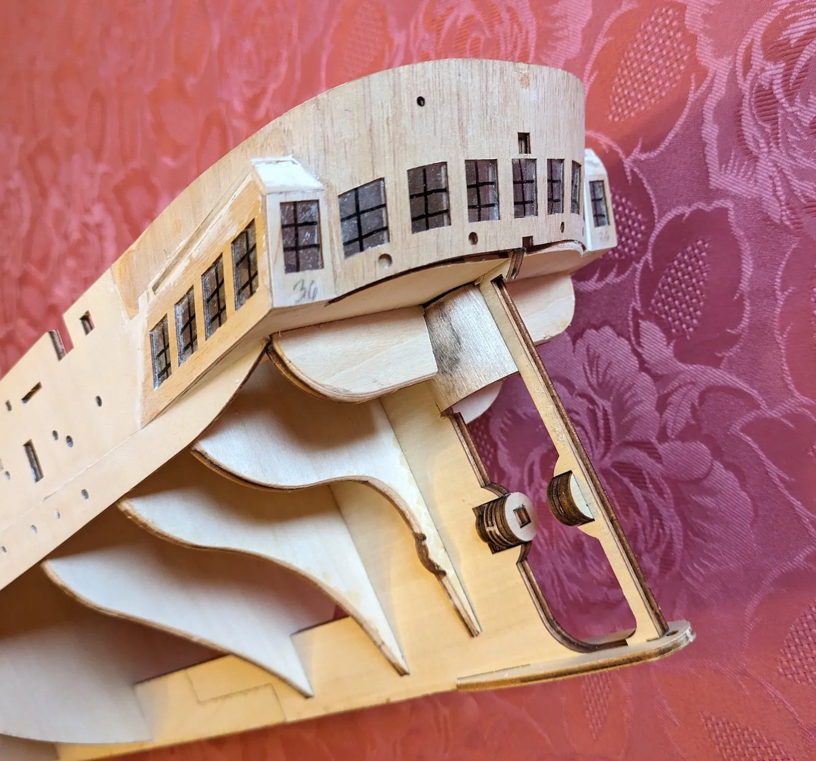
In the real HMS “Warrior” the stern galleries aren’t all they seem. In a sailing warship these galleries give onto the spacious Captains’ cabin, giving him a panoramic view. But in “Warrior” not all is as it seems. Behind the windows is located the upper part of the propeller trunk. “Warrior” was of the “up funnel down screw” era. When under sail the 26 ton 2-bladed propeller could be lifted within a trunkway, reducing drag. The propeller was fitted within a vertically sliding “banjo” frame which itself weighed 8 tons. It took the whole crew around half-an-hour to raise the propeller. When lifted there was still a portion of the lower blade in the water, but drag was reduced significantly.
In the model the stern galleries are constructed from a series of precision -cut parts. Firstly, the counter stern shell is constructed. This is formed from two sheets of ply, pre-formed with all window apertures pre-cut. The inner laminate is applied first, after steaming to the required curve. When secure, the outer laminate is attached. The windows are represented by a sheet of clear acetate which is carefully marked with the glazing bars. The acetates are cut to shape and carefully glued to the inner face of the outer laminate. This is then glued onto the inner, care being needed to ensure the window apertures co-incide. A small amount of fettling and filling is needed to fair this assembly into the existing topside.
Model of HMS "Warrior" - 1


The side galleries are now constructed. The parts are prepared and cleaned up. Side- and aft- facing windows are fitted as described above, and the parts carefully glued into position. Again, a small amount of fettling is required to obtain a perfect fit, with a minimal amount of filling to make good. At this point it is advisable to paint the internal structure of the hull in the stern area matt black, otherwise the structure might be visible through the windows. After planking is complete, of course, it is not possible to do this.
It is now necessary to complete a few details around the sternpost. A sole piece is fitted to the lower part of the stern frame, and a series of small discs are fitted to comprise the propeller bossing. It is now necessary to construct the propeller housing. As mentioned before, the propeller on this vessel is intended to retract upwards into the counter. A flat rectangle of ply is steamed and formed into a flattened cylindrical shape. This is fitted into a recess in the upper part of the stern frame. In this case the rectangle of ply was not quite long enough, requiring a small amount of fiddling to obtain a good visual fit.
The inner bulwarks were now fitted, in five sections. Again, very precisely laser-cut with all the cut-out ports matching those in the outer bulwarks exactly. The stern section fitted easily without having to steam the component.
The upper part of the hull is now substantially complete, the next job is to plank the lower part of the hull, beneath the waterline.
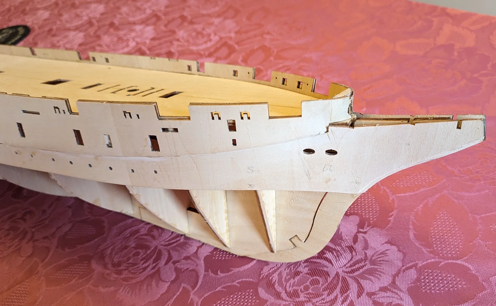
The planking is straightforward. Lime strips 6mm x 1.5 mm are provided for the hull planking. A small number required steaming in order to achieve a good fit at the stern, beneath the counter. The normal array of short planks and stealers need to be fitted to complete the shell. The run of planking is unimportant in this vessel, as we are actually simulating a hull constructed from iron. Once planking is complete the hull will be filled and sanded smooth with no visible trace of the individual strakes. This process takes time and patience. When planking is complete, the hull surfaces will show considerable roughness and unevenness. It is important that, prior to commencing planking, the frames and bulkheads are carefully bevelled. Even so the finished planking will show irregularities which must be filled and sanded. The same applies to full-sized wooden construction hulls. The shipwright would systematically work around the whole surface of the hull with his adze and plane. In Lowestoft shipyards this was known as “scrubbing down”. Hard, back-breaking work. Fortunately, easier for us model-making types!
Once the “scrubbing down” is complete, the hull can be given a coat of primer, and she begins to look like a warship! That’s the first stage of construction complete. The hull can now be brought iinto the infamous kitchen shipyard for fitting out and rigging.
End of part 1
Part Two


Whilst building the hull of HMS “Warrior”, I briefly thought about making her a powered working model. This is quite feasible; the hull is plenty large enough to house all the power, steering, radio and batteries. “Warrior” would be an impressive presence on any pond. In order to convert her into a working vessel, however, a considerable re-working of the basic hull framework would be required. I didn’t consider this possibility until I was well underway with the construction, so decided against that project.
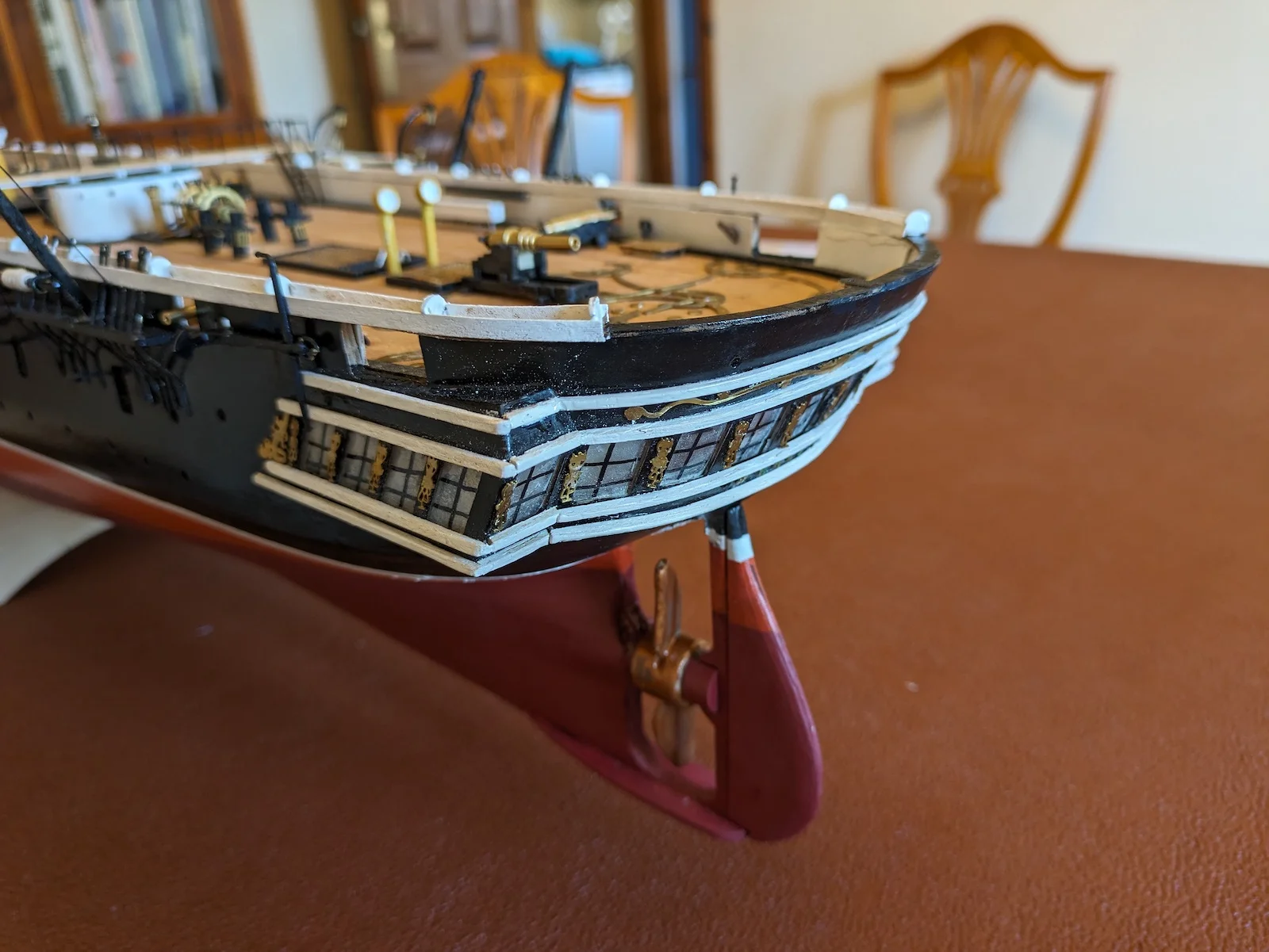
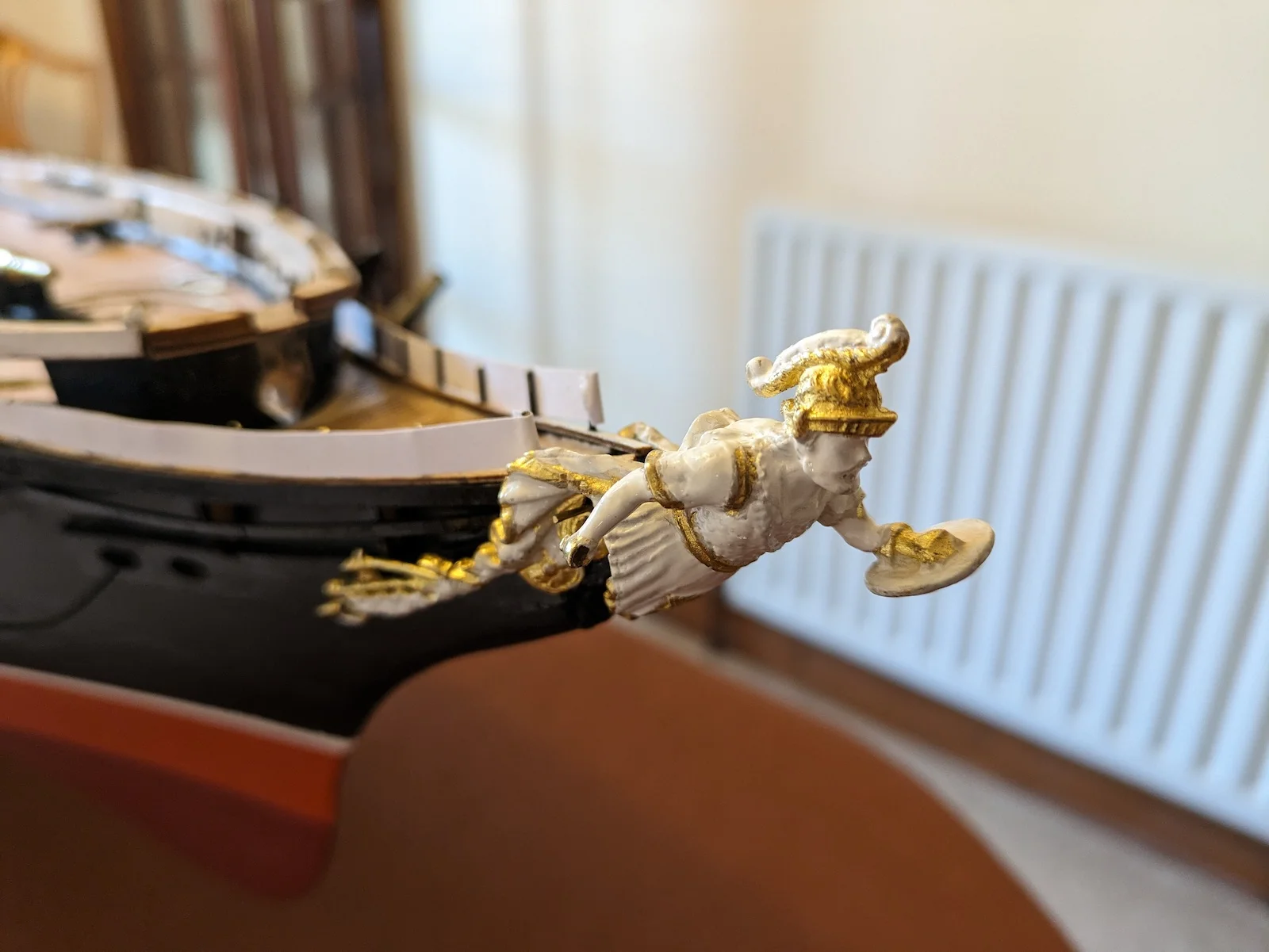
So far, the hull is structurally complete, primed, and ready for external and deck fitting-out. Fore, main and mizzen chain-plates were fitted, and the beak-head structure installed at the bow. Care must be taken in order to get this latter structure “right”; several small parts must be fitted just so, including the pre-formed lattice grating. It is important that the overall width of the beakhead at its forward end is no more than 5mm, as indicated in the drawings. This is in order to allow the fitting of the figurehead. This latter is a magnificent lost-wax casting of (what else?) a Warrior. Once a dry fit is ensured the figurehead casting can be set aside for painting, and fitting at a later stage.
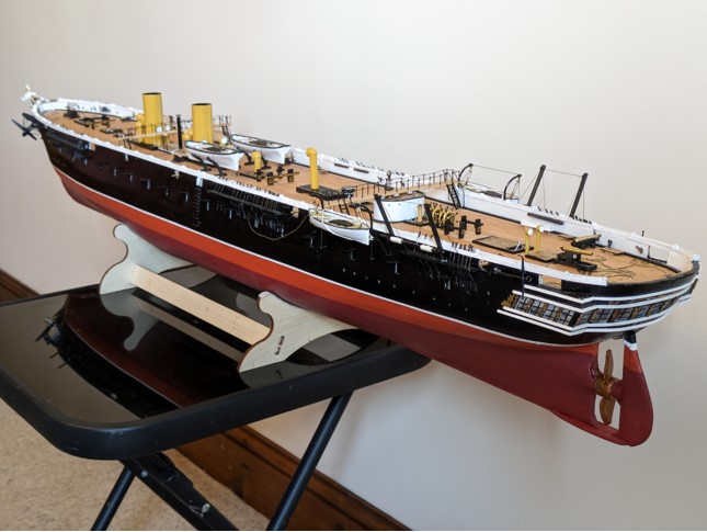
The hull was finish-painted at this point. The topsides in satin black, the bottom in red “antifouling”. Very careful masking allowed the application of a sharp white line 3mm in width at the waterline.
The simple stand was assembled and glued at this point. I modified the stand for the hull construction process. I cut strips of egg-box fibreboard and glued these to the hull support surfaces on the stand. During construction, the hull can sit on the stand, and can be heeled to any angle for convenience. The cardboard surfaces protect the painted hull from damage.
The next task is to undertake the planking of the deck, but before we start it is necessary to complete the margin strake and the covering boards. The first task is to paint the inside of the bulwarks. This in my case needed two coats of matt white followed by the finish-coat of white gloss. This needs to be completed and dry before fitting the margin strakes. These latter are pre-formed laser-cut strips of 3mm ply, six in all, shaped to fit snugly against the inside surfaces of the bulwarks. After dry-fitting, these are painted black before final fitting in position. It is important to paint first, as it would be impossible to do a neat black paint job without ruining the white bulwarks. Once fitted, the outer strake of deck planking can be fitted, following the curved line of the inner edge of the margin strakes.
Deck planking is provided in the form of 600mm lengths of 5mm x 0.6mm wood. Starting with the king-plank, laid accurately down the centreline, all the planking runs fore-and-aft. The temptation is to lay the planking in long lengths, but I opted to use shorter planks of around 80mm, each one butting against its fore- and aft neighbour. If using this technique it is necessary to carefully plan the layout of the “shift of butts”. I used a three-strake shift, staggering the butts equally; every third strake has the butts adjacent. There are many apertures on the centreline, so it is necessary to plan the planking layout in advance. It is easy to make a mistake here and ruin the symmetry of the job. Once planking is complete, it is sanded smooth and given two coats of Humbrol clear Flat Cote. This gives a fair representation of the holystoned teak laid deck in the full-sized vessel.
Next to be fitted are the bulwark cap rails. These are provided in the form of six laser-cut sections. The top edge of the bulwarks need to be trimmed level to provide a fair surface on which to glue the cap rail sections. It is advisable to paint the cap rails white in way of the chainplates. It would not be possible to do this neatly once the chainplate straps (black) are fitted.
Now we must tackle the task of shaping and fitting the chainplate straps. These are the iron straps securing the lower ends of the standing rigging. There are 84 in total; 16 each side on the fore and main, and ten each side on the mizzen. Be careful not to lose any, as no spares are provided. It is advisable to paint these black before fitting. The chainplate straps are carefully bent to shape, passing through pre-formed holes in the chains with the lower 6mm resting snugly against the hull side. (The “chains” are the wooden platforms mounted outboard of the hull plating giving extra “spread” to the chainplates). Above the chains, the straps angle inboard in order to line up with the shrouds and backstays. Pre-formed slots in the cap rail ensure the correct fore-and-aft angle of each strap. It is important that each strap locates snugly into its slot, otherwise they would interfere with the fitting of the upper sections of bulwark. I found that the best way of fitting the chainplates is to bend each one with pliers (double bend) then drop the chainplate into it’s allocated slot in the chains. Then drop the chainplate right down until the eye at the top is resting on the chains. The correct bend can then be carefully applied to the chainplate with snipe-nosed pliers before pulling it back up to it’s final location. This way it is possible to obtain a snug fit of the lower section against the hull, with the upper end snapping positively into the cap rail slot.

It is important to study the drawings most carefully at this point. The provided “instructions” consist of a series of detailed drawings showing each stage of the construction. It is not immediately apparent exactly how the upper bulwarks are arranged. Reference must be made to later drawings in the booklet which show the final configuration. The cap rail is surmounted by two vertical strips forming a channel section atop the bulwark. The outboard strip is 0.8 x 4mm located onto the outboard face of the cap rail; while the inboard strip is 0.8 x 3mm strip secured atop the inboard edge of the cap rail. These two strips are reinforced by a series of spacers, 32 each side. All of this is a really fiddly piece of work and care must be taken in order to “get it right”. Once assembly is complete the bulwark structure can be carefully cleaned and sanded, and finished in gloss white.
We can now commence the construction of all the deck fittings and fixtures. Care must be taken in the painting of each assembly. Some parts need to be painted before assembly then maybe touched up afterwards. It is necessary to “think ahead” with the process.
At this point, mention must be made of the procedure necessary to assemble the parts for each fitting. This is a bit involved and tedious. The illustrative instructions, parts listing and diagrams showing each plywood fret are all bound together. Taking one deck assembly, for example the Capstan, the construction diagram shows about twenty separate parts, each numbered. It is necessary to make a list of these parts, then look up each part in the parts list elsewhere in the instruction book. This listing will indicate for each part which numbered plywood fret panel that part is located. The instructions illustrate all the plywood frets, each numbered, and it is necessary to locate the numbered part on the particular fret. After locating the actual fret, the individual parts are identifed and carefully detached. It is important to write the part number on the part, otherwise parts can become lost or transposed. The part numbers, and the fret numbers are not marked on the frets. While this is inconvenient, I would guess that it is not possible to mark the numbers, as they would end up being laser-cut.
A large number of gratings need to be assembled. Laser-cut grating frames and grating panels are supplied within the frets, and need to be identified, separated from the frets and cleaned up. The actual grating panels have holes which are precision laser-etched. These need to have the holes opened up to remove all the approx 1mm square plugs. I use a small pin-chuck with a 1mm drill bit inserted back-to-front. Each plug can be very carefully poked out. Once this has been done the ply has invariably de-laminated. This isn’t a problem. After cleaning them up I glue them onto a cardboard backing which I have covered in black ink from a marker pen. This gives a black background beneath the gratings. Again, I write the number of each grating assembly on the back of the card base. The grating panels are varnished while the grating surround frames are painted gloss black. Finally the frames and panels are glued together ready for locating on deck. This is a time-consuming process but if done carefully yields a smart result.
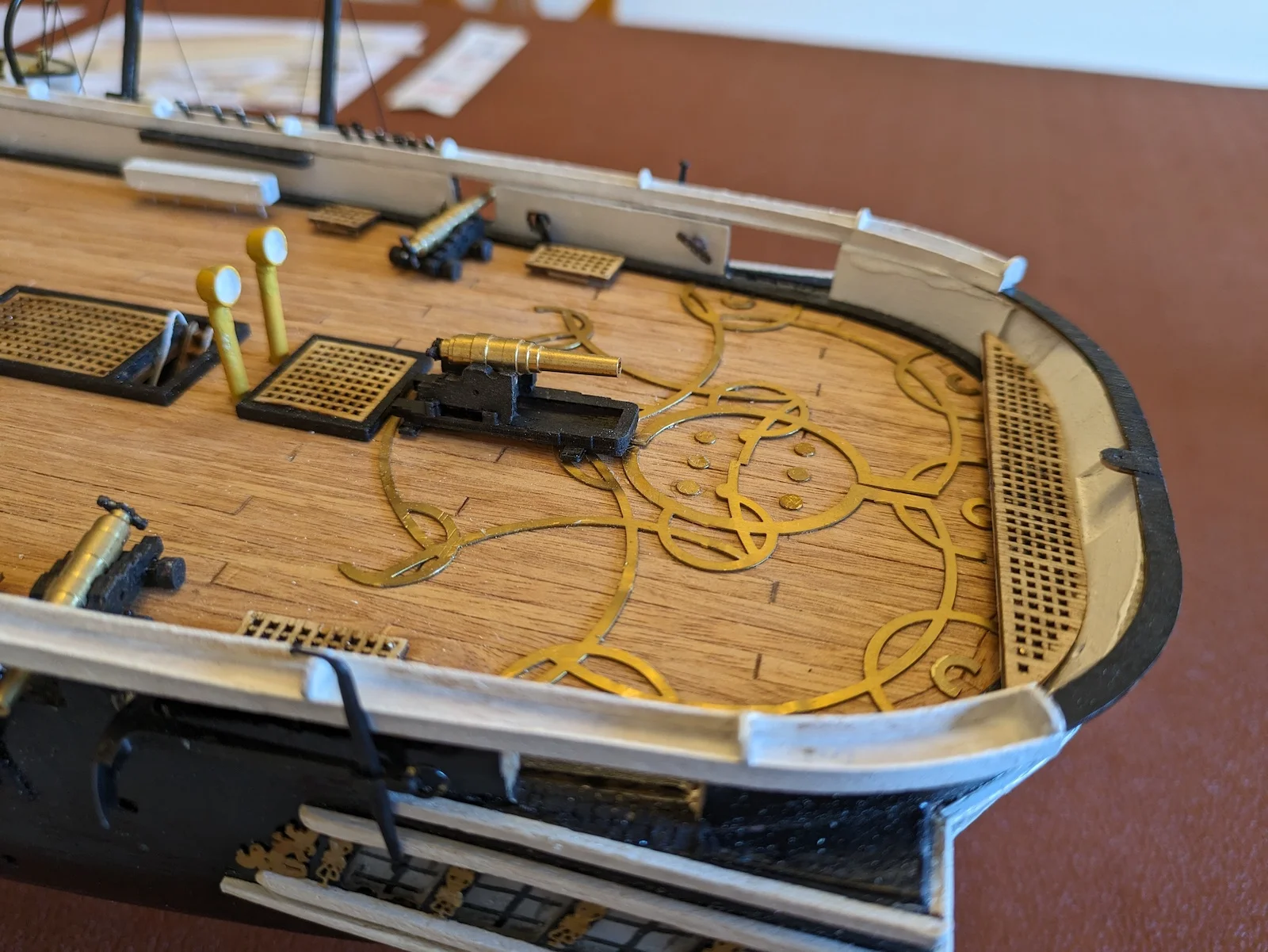
Cowl ventilators are now assembled. The brass cowls are provided in the kit, together with a length of 7mm brass tube. Twelve ventilators are required, of two different heights. The tube is carefully cut at 30° to the exact length. Care must be taken, as there is no spare tube! After cleaning up the ends of the tube with a file, the end was plugged with wood and filed to form a secure surface for glueing the cowls. After cleaning up, the ventilators are painted yellow, with white cowl interiors.
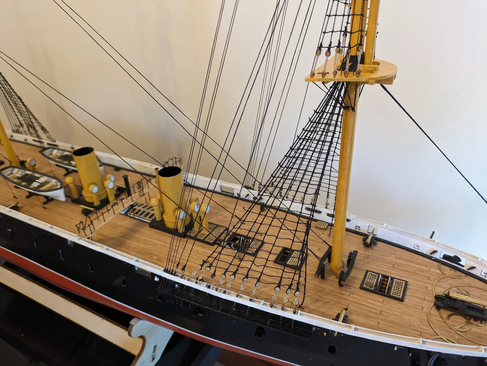
A number of sub-assemblies are now constructed, including the boiler room skylights and boiler casings. The latter will house the funnel bases and the boiler room ventilators. The funnels are assembled onto the casings after painting the correct shade of deep yellow. Steam pipes are also fitted and painted the same colour. Once all of these fittings and assemblies are complete, painted and dry, they can be carefully located in the correct positions on deck. Reference to the full-sized deck plans will assist with this.
A number of companionways (staircases) need to be assembled, painted, then fitted in the appropriate openings. Handrails need to be fitted to each. The instructions suggest fitting stanchions made from 0.8mm brass wire to the top and bottom of each set, then using fine thread to connect the tops of the stanchions forming the handrail. I simplified matters by forming a one-piece rail from wire, shaped to fit into the steps top and bottom. Once assembled and painted these stairways can be very carefully glued in place. Great care needed here to avoid “losing” any of the assemblies inside the hull.
Next to fit are the brass gunrails or “races” on the bow and stern decks. These are intricate slideways allowing the guns to be trained. “Warrior” was an extremely innovative vessel, with breech-loading guns, but the turret had not yet been developed. So, although the guns were a great advance upon the muzzle-loading units firing solid shot of the earlier era, there was still some way to go toward the arrangements in the later ironclad battleships.
The races are provided as precision brass etchings. These need to be identified, separated from the brass former, cleaned up and carefully located. Again, essential to get the locations correct; reference to the deck plans again.
A few minor fittings; rudder and propeller, flag lockers, anchor cat-chocks and the pinrails around the masts. These latter are quite complex, with tiny brass inserts. It is necessary to look ahead here. Many rigging elements will be secured onto these pinrails, and although this is “only” a model, the combined upwards pull of all those lines could easily pull the pinrail assembly off the deck. This would be a modelmaking disaster! After completing a lot of rigging, leading each line down to the correct belaying-pin and making fast, to have the whole assembly pull off the deck is annoying to say the least, and very difficult to rectify without stripping out and starting again. I took steps to ensure the pinrails were secured to the deck a bit more substantially than suggested in the instructions.
The next major assemblies are the compass-platforms or flying bridges, of which there are two. These are light platforms spanning the width of the vessel, located above the main deck. Supported on stanchions, they carry two of the magnetic compasses used for navigation and steering.
The platfoms are based on laser-etched ply platforms which are cleaned up and planked on the upper surfaces. Holes are located for the various support stanchions and handrail stanchions. Painted white on the underside, and flat varnish on the upper surface, an important detail must be added. In the real ship, these platforms are surrounded by a yellow-painted cast iron “rope” decoration. It is necessary in the model to take a length of 1.0 mm rigging thread, paint yellow, leave to dry, then carefully glue around the edge of each platform.
Now comes the fiddliest job so far. Brass wire stanchions must be made (0.8mm) to support the platforms. These have a 90° bend at their bottom end, locating into holes pre-drilled into the inside faces of the bulwarks. The forward platform also has four vertical stanchions locating into holes drilled into the deck. Great care needs to be taken at this stage, resulting in the platforms secured at the correct height, square to the centreline, and level port/starboard.
Next, the compass platform handrails need to be fitted. Stanchions are cut exactly 12mm in height, painted black. These are carefully fitted in position, making sure they are all vertical with the top ends level with each other. The kit calls for the handrails themselves to be formed from 0.8mm brass wire, bent accurately to shape, and secured atop the stanchions. Here, I deviated from the instructions. I found It utterly impossible to glue these rails securely in place. Ultimately I formed the handrails from 0.5mm rigging thread. A round-turn round each stanchion, tease the thread right to the top of the stanchion, and a touch of glue. Don’t forget to leave the gaps where the ladders give access to the platforms!
It’s a real pity that the kit did not include proper 10mm single-hole brass stanchions for this task. That would have made the job much easier, with a more visually satisfactory result.
The four ladders giving access to the compass-platforms are formed from brass etchings which are folded to give individual steps. These are made, painted and installed. The instructions make no provision for handrails for these ladders, but I made such from 0.8mm brass wire, bent to shape and planted into holes drilled into the deck.
The compasses themselves were assembled, painted and installed. Once they were in position, I have to admit the platforms looked very good. Worth taking the trouble to “get it right”.
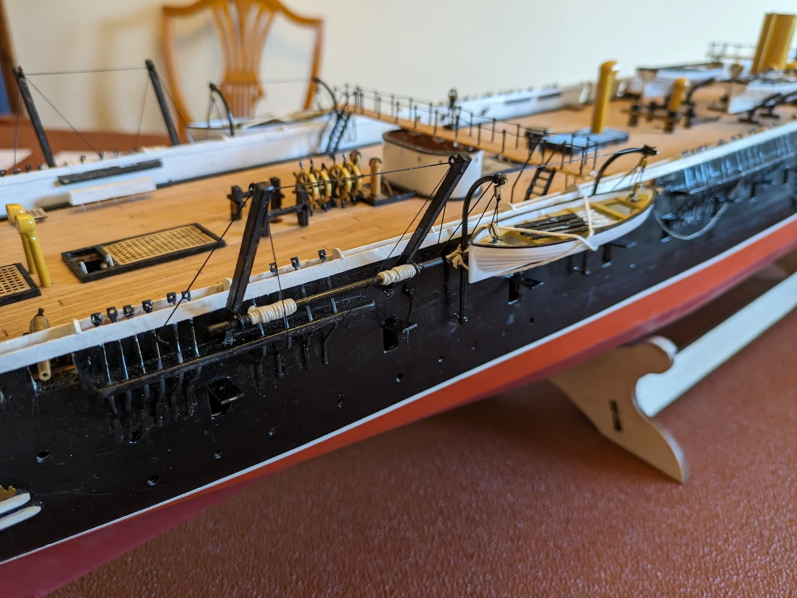
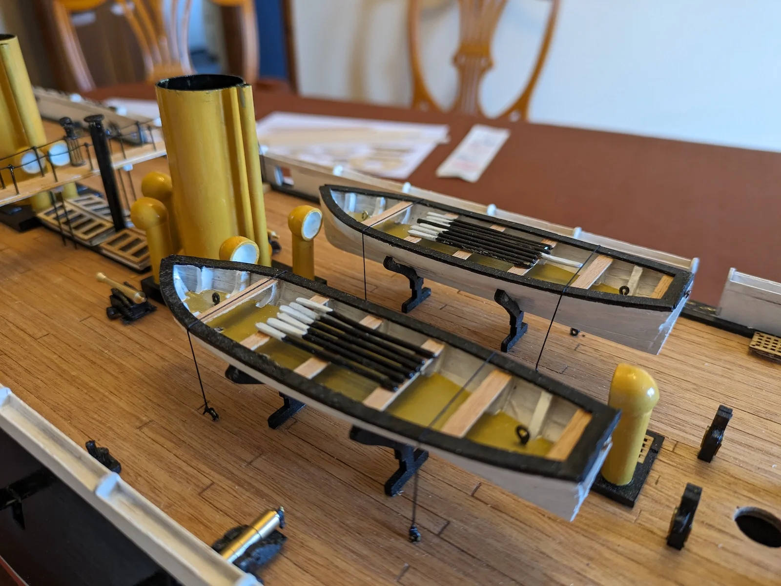
The next task was to complete and install the four boats. Two 32 foot galleys are suspended from radial davits aft, while two 42 foot launches are stowed on cradles amidships. The galleys were provided as plastic mouldings which had to be fitted-out with thwarts and floorboards. Radial davits were formed from brass wire, provided with single fall blocks at their heads. The davits were secured to the ship’s side using brass wire eyelets inserted and glued into holes drilled into the shell “plating”. Care was taken to get the davit curve to the correct profile, and to mount them at the correct height. In the kit drawings the rigging of the boats is somewhat rudimentary; only lowering falls on two single blocks being portrayed. As a retired master mariner, I felt more appropriate rigging was indicated. Davits were provided with guys and span-wires, and proper griping spars were made and fitted. These latter are horizontal spars fitted with cylindrical white fenders, secured to the davits at deck level. When stowed, the boats rest on these fenders. The boats are provided with diagonally rigged gripes, pinning the boat to the ships side. Painters (bow ropes) are rigged leading forward and made fast on deck. Each boat was provided with a set of oars.
A further pair of davits is located abaft the galleys. These are fixed spar davits fitted into recesses in the topside, rigged with span wires, guys and topping lifts. The latter support the upper ends of the davits, running diagonally upwards to the mizzen mast top. Since the mast is not yet stepped, these davits are very vulnerable. Care must be taken to ensure that they are not damaged whilst continuing with the construction of the ship. Griping spars are not specified in the instructions, but are easily made and fitted to these fixed davits.
The larger launches are built from wooden components. Several laser-etched parts form the framework of the boat, which must then be planked. This is a very fiddly job, but care taken here produces a pleasing result. Again, I decided to add further detail. The launches were fitted to their deck cradles, and four eyebolts were fitted into the deck adjacent. Once the boats were secured to the deck, gripe wires could be rigged securing the boats in position. Again, a set of oars was provided for each boat. Oars were made by hammering the end 10mm of a length of 1mm brass wire, then cutting to length. Oars were painted black with white blades, stowed in the boats with blades forward.
Lower deck gunport doors were prepared and fitted. I toyed with the idea of fitting each with two support wires, but decided against.
Four anchors are provided; two main bower anchors forward, two smaller stream anchors aft. The latter are simply glued in position, but the bowers are to be properly “catted”. In addition to the anchor hawser leading from the hawsepipe, the anchors need to be rigged with three-fold blocks. Vertical holes in the cathead allow for the anchor to be correctly suspended by a threefold cat-tackle. The inboard fluke of the anchor is secured at deck level. All a far cry from modern arrangements with stockless self-stowing anchors with a powerful windlass. Although “Warrior” is steam powered, her anchors are weighed by hand by large numbers of matelots manning capstan bars. Incidentally, modern mooring arrangements have the vessel secured with chain cable fore and aft. Originally, “Warrior” would have her bower anchors secured to cable-laid rope hawsers. Chain-making technology was a few years in the future.
“Warrior” was equipped with a variety of guns. She represented a transition from traditional smooth-bore muzzle-loading cannon firing solid shot (cannonballs) to more modern breech- loading guns with rifled barrels, firing explosive shot. The more familiar turreted guns lay in the future. “Warrior” had thirty 68 pounder muzzle loaders plus eight 110 pounder Armstrong breech-loaders on her lower deck. These do not feature in the model. On deck, two 110 pounder breech loading Armstrong guns are mounted as chase guns; one forward, one aft. Other guns firing broadside are 68 pounders, and two smaller saluting cannon are fitted. In the model all these guns are assembled from precision cut parts with turned brass barrels. In the vessel, all guns are painted black (they are resin-cast replicas) but I decided to use a bit of model-makers licence, and painted the carriages black, leaving the barrels shiny brass. Not authentic but looks good!
The final task is the fitting of the figurehead. Depicting – what else? – a warrior, the figurehead is a very detailed lost-wax casting, only requiring painting. In the prototype vessel the figurehead is painted white with much detail picked out in gold. An hour with a very fine paintbrush yields a very satisfactory result, and when fitted gives the vessel a very distinguished appearance.
That completes the hull and deck outfitting. Next we turn our attention to the masting and rigging, or “the stick and stringy bit” as my wife likes to describe it.
End of part 2

Model of HMS "Warrior" - 2
Part Three


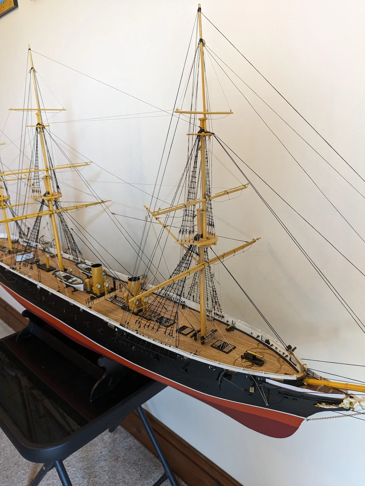
“Warrior” is rigged as a conventional three-masted ship, that is, square-rigged on all three. At the time there existed huge prejudice against steam power amongst senior officers in the Royal Navy. Sail had reigned supreme for hundreds of years, and steam was regarded with great suspicion. Apart from anything else, huge quantities of coal required to be carried and handled with the consequent coal dust and soot soiling the pristine paintwork and scrubbed teak decks. Coaling ship was a perennial task, resulting in the ship and her crew being saturated in coal dust. New skills were needed among the crew and officers. Engineers and stokers were a novel addition to the ships complement. Early steamships suffered reliability problems, so a substantial sailing rig was retained in early steam warships. The sailing rig of “Warrior” is not as lofty as it would have been had she been a pure sailing vessel, but nevertheless she was capable of a decent sailing performance under sail alone. “Warrior” was one of the vessels in which the order “up funnel down screw” could be heard. When under sail the huge propeller could be hoisted into a trunk in the stern; the lower blade was still in the water but drag was reduced substantially. The process to lift the propeller was totally hand-powered, and it was necessary that the whole crew were used to raise the 22-ton propeller.
The Billings kit is configured to portray the vessel with full standing and running rigging. Sails are not included. This conforms to the convention I have always followed in the construction of static model period sailing vessels. If the vessel is portrayed as a full-hull model mounted upon a keel stand, then sails should not be included. On the other hand, if the vessel is shown as a waterline model, set in a realistic sea, then sails should be set and drawing, and the vessel heeling to the breeze.
In the model kit, masts and spars are provided in the form of a set of dowels of appropriate sizes. An instruction leaflet shows each mast as component parts, standing rigging, and running rigging. Each component needs to be identified, with dowels cut to length. The lower mast and topmast platforms (tops) are constructed from laser-cut wooden parts, as is the bowsprit. The latter is constructed as main bowsprit, jibboom and flying jibboom. Some spars need to be tapered. I did this on my lathe, but it can be done by careful sanding. Once all masts and spars are assembled, with construction of lower and topmasts complete, all spars can be painted yellow.
My breakfast-bar shipyard is now converted into a rigging loft, and the job of making up all the stays comprising the standing rigging commences. Standing rigging is the variety of stays, and shrouds which provide permanent support to the masts and bowsprit.
I always rig the vessel in much the same sequence that would have been adopted in the real vessel. Lower masts first, then the standing rigging on those masts before moving upwards to the topmasts. “Warrior” had her standing rigging tensioned and secured using deadeyes. Bottlescrews were not adopted for some years yet. Although “Warrior” was a technological revolution in many ways, there were many aspects of her design and construction reflecting the earlier era of wooden hulls and sail.
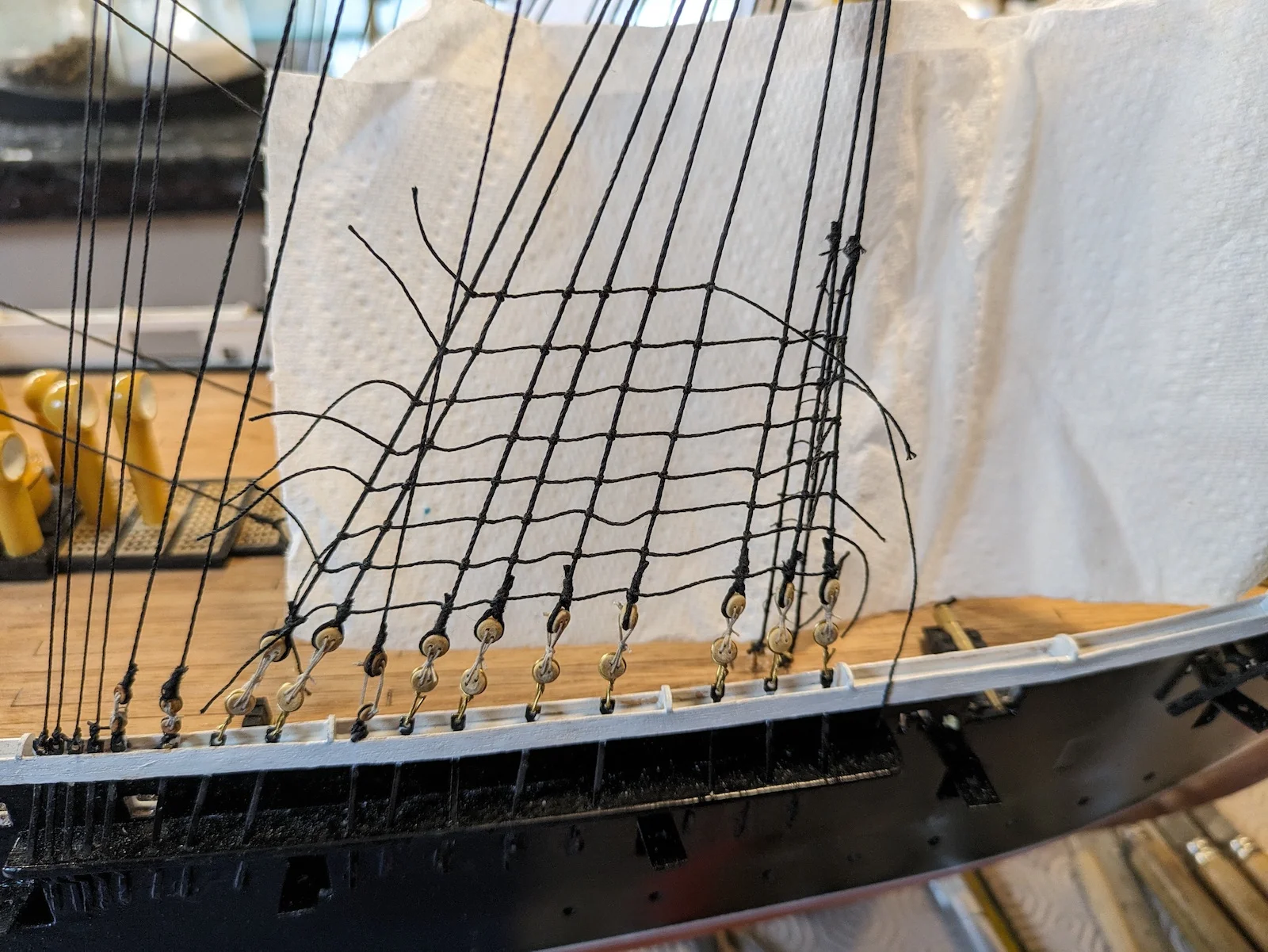
Deadeyes now need to be located onto the tops of the chainplates at the gunwale. I used fine (0.5mm) brass wire, circling each deadeye, twisted to secure then fitted to the chainplate with a further twist. Care must be taken to ensure that the correct size of deadeyes are located onto each chainplate; large ones for the lower stays, smaller ones for the upper. Reference to the drawings essential. While I was undertaking this task I also fitted small deadeyes to the mast top platforms, together with their corresponding futtock shrouds.
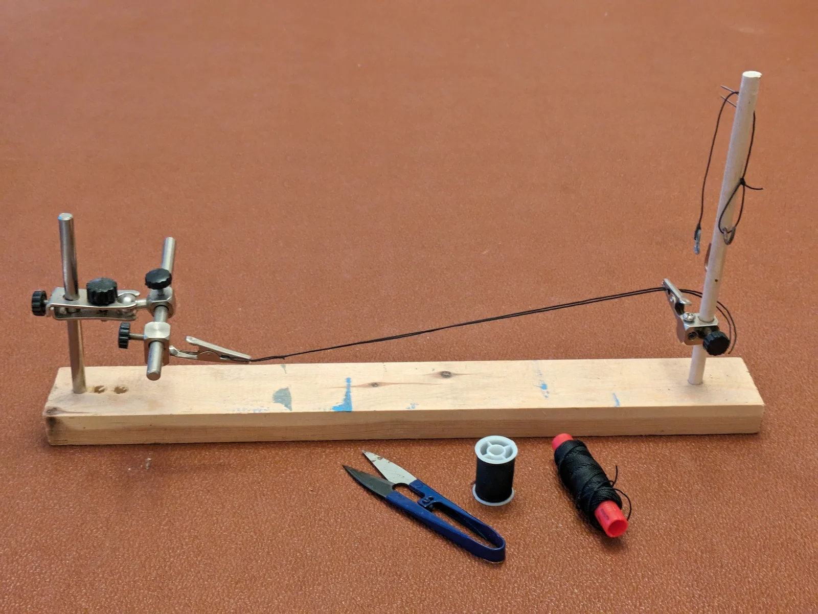
For help with rigging tasks I have made a little jig on which individual elements of rigging can be made. Support hooks and crocodile clips allow a length of rigging cord to be held while I work on seizing eyesplices and deadeyes.
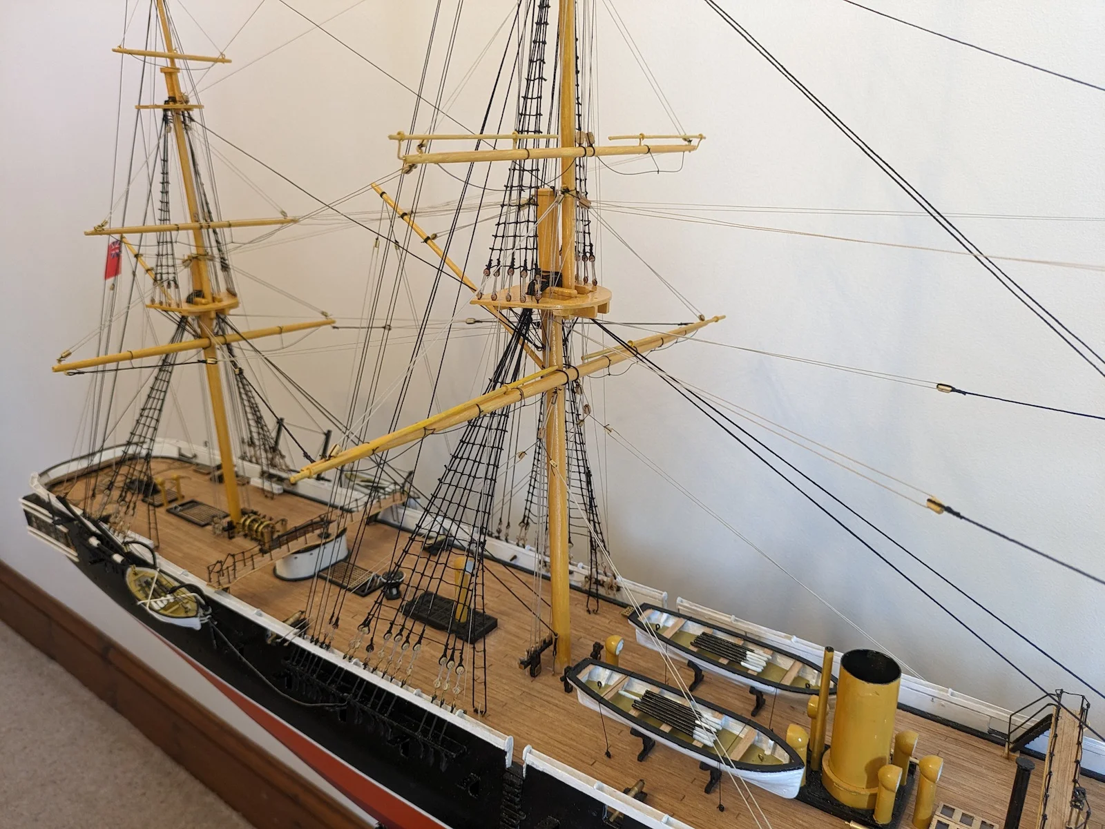
“Warrior” is heavily rigged, despite her sailing rig being auxiliary in nature. Fore and main lower masts each have nine shrouds on each side, each of which is eyespliced at the upper end, the splices dropped over the masthead in order. This order is known as the “dressing order”, and normally starts with the forward starboard pair of shrouds, next the forward port shrouds, then working starboard/port working aft. The final item is the double forestay.
Each shroud needs to have a deadeye seized onto the end. One of the most difficult jobs is to get all the deadeyes in line horizontally when rigged and set up. Starting with the forward pair each side, the shrouds are temporarily rigged and marked for length. Deadeyes are seized into the shroud pair at exactly the same length for each side. Lanyards are fitted, and the mast located. The deadeyes are rove onto their corresponding members on the gunwale. Hopefully, this should give two deadeyes each side level with each other. Having rigged this pair, ensuring the mast is perfectly vertical, the remaining shrouds can be made and rigged. Each “leg” needs to be a fraction longer than the last, as the lead becomes progressively further aft, also, each pair has its “splice” resting atop the previous one.
Patience required, 54 shrouds and forestays to rig for the lower masts only. These are set up and secured temporarily. Rigging will always slacken off with time and during construction, and adjustments will be necessary.
I make up a small pot of dilute PVA wood glue, half-and-half water, which I use to “paint” rigging knots to ensure that completed rigging doesn’t inadvertently unravel.
Once the lower masts are set up and rigged, the bowsprit can be made and fitted. This is formed from three spars; bowsprit, jibboom and flying jibboom. To fit these components together I drill 1mm cross-holes through adjacent spars, and secure with 1mm wire rods. A chain bobstay is fitted beneath the bowsprit, leading to an eyebolt fitted into the stem at the waterline level. This bobstay will need adjustment and tightening at a later stage, so is secured temporarily. Ghe remainder of the bowsprit rigging is straightforward.
Once all lower mast stays, including forestays, are fitted and rigged, topmasts can be stepped. Again, these are secured by cross-drilling and inserting 1mm wire pins. The topmasts have already been constructed, complete with their doubling and tops.
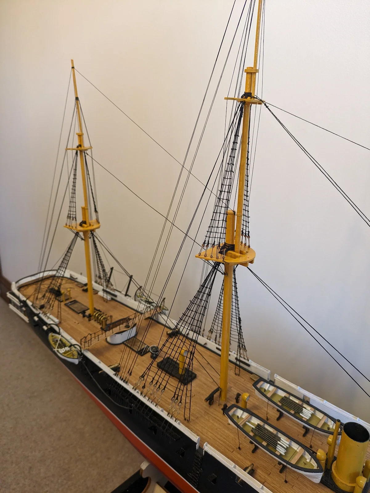
Starting from aft (the mizen mast) topmasts are rigged with shrouds leading to the lower mast platforms, and backstays leading to the appropriate deadeyes on deck. All deadeyes are rove with their lanyards, but not yet permanently secured. Topmast forestays are rigged according to the plans. Finally, topgallant masts are stepped and rigged. No deadeyes this time, and lighter thread used for the shrouds, forestays and backstays.
Once all stays are in place then the rig can be set up tight, adjusted and secured. Start again from aft, continually checking for the correct rake, and all masts transversely vertical. Often, tightening one stay pulls some slack in others. Considerable adjustment may be needed to achieve the required result. The final adjustment will be to tension the chain bobstay. A threaded purchase is formed at the lower end, onto the stem eyebolt. This allows the bobstay to be tightened and secured. This act will take up the slack in all shrouds and backstays on all three masts.
Once all this is complete, all rigging can be secured, then all rigging thread connections can be “painted” with the 50/50 solution of PVA glue with water. This prevents knots and hitches working loose. When dry, all loose ends of thread can be carefully trimmed off using snips. I say “carefully” as it is essential that no “accidents” occur, such as clipping the wrong line. A useful technique is to keep the snip blades closed right until they are positioned at the line to be clipped. This prevents inadvertently cutting another piece of rigging.
The next job is to rig the ratlines. This is a long and tedious task but needs to be done with care. The finest thread is used, creating “rungs” no more than 6 mm apart vertically, clove-hitched to each shroud. It is important that all ratlines are level and horizontal. I find it advantageous to prop up a piece of white card or paper behind the bank of shrouds being worked upon. This allows a much better view of the work.
In a real vessel, the job is known as “rattling down” , although, always starting at the deck and working upwards, I guess it ought to be “rattling up”. Leave about 20mm loose end at each end of each ratline. This allows you to hold the end with tweezers while trimming off the excess with the snips. Before trimming, apply PVA solution to all the ratline knots and allow to dry. It is worth spending an hour or two at this stage, inspecting all of the completed standing rigging. Invariably a few knots and fastenings will have worked loose and require remedy. A cocktail stick with a dab of superglue comes in handy. Some rigging may have become slack, a few deadeyes may need to be retightened and secured.
That is the standing rigging complete, and she is beginning to look like a ship! But we still have much to do. We have the yards and other spars to fit-out and locate in position, then all the running rigging to tackle.
Before any running rigging can commence, the yards and gaffs need to be “fitted out”. So far they have been cut to length and tapered where necessary, then painted yellow. Reference to the rigging drawings will indicate where blocks need to be secured and wire eyelets fitted. The fore and main lower yards carry stuns’l (studding sail) booms. Brass wire eyelets are made and fitted at the yard ends and quarters to take the booms.
The rigging plans provided with the kit omit a number of items. There are no footropes beneath the yards, and no braces on the mizzen. I decided to add these features, as a square-rigger doesn’t look right without them. In my time at sea I have sailed in square-rig, and cannot contemplate working aloft without footropes on the yards. These are the ropes that the crew stand on when out on the yards furling or reefing sail. I made the footropes themselves from ‘Trimits’ craft stainless steel wire, plastic coated. This is obtained from a craft shop, and normally used in jewellery making. It provided exactly the right stiffness to simulate a rope hanging below the yard. The footropes are attached to the yard at intervals by vertical “stirrups”; short lengths of rope holding the footrope a fixed didtance below the yard.
Commencing with the three lower yards, brass wire pins are fitted in their centres, facing aft, fitting into holes drilled into the mast at the correct height. The truss on which the yard pivots is simulated using black rigging thread. Braces and lifts are rove taking care to ensure a fair “lead” to the pinrail on deck. Yards are carefully set up to be perfectly horizontal, and square to the centreline. Braces and lifts are tightened and set up.
Once satisfied that all three yards are square and level, the lifts and braces can be secured. I don’t even attempt to belay the rope to the belaying pin in the normal manner. I pass the rope through the hole in the pinrail, then apply a smudge of glue to the belaying pin, pushing the pin into the hole securing the rope in place. It is necessary to ensure that this “belay” is correct, as, once the pin is glued in place, it cannot be undone! The spare end of rope is cut off short. No attempt is made to coil it up and hang the coil on the belaying pin as in full-size practice. I make separate coils of the same thread to hang on the pins once all rigging is complete. I will describe their making later.
Gaffs are fitted on all three masts. Each gaff is secured to the mast with a short length of brass wire; making a working gooseneck is not feasible at this scale. The gaffs are supported by a halyard using several blocks, and two vangs control the peak of the gaff. In hindsight, I would rig the three gaffs first, before fitting the three lower yards. I rigged the yards first, which made access difficult for the gaffs.
With any running rigging element, care must be taken when running the hauling part from its block aloft down to its belaying pin on the appropriate pinrail. For upper yards, this is sometimes a tortuous route, ensuring that the lead doesn’t foul any other rigging elements. Once in place, and before finally securing, I hang the spare end over the ship’s side, and hang a clothes peg on it. This provides temporary tension on the line while other lines are rigged. Once all are rigged, adjustment can be made until all is fair, yards level and square. Then halyards, lifts and braces can be secured permanently.
One of the final details is to hoist the red ensign at the spanker gaff. An alternative location is the taffrail staff, but this is very vulnerable, so I opted to show it on the spanker peak. A question might arise as to why a Royal Navy ship should fly the red duster; this flag universally flown in merchant vessels. But not in 1860. “Warrior” was the flagship of the “Admiral of the Red”. The navy comprised thred fleet divisions; Red, White and Blue. Vessels wore the ensign of the division to which they were attached.
Once all running rigging is complete, it is necessary to make several dozen tiny coils of rope to hang onto individual belaying pins. These simulate the lengths of spare line coiled up and stowed. I made a little jig with sets of three pins close together. A length of rigging thread is wound around two of the pins, with one turn around the third pin. This forms a coil of rope with a single loop to hang onto the belaying pin. A smudge of glue helps the coil to “hang” correctly.
It is now necessary to go over the whole rig to check all is correctly secure. Once satisfied that all is in order, a final job is to go over all knots, hitches and loops with dilute PVA glue applied with a small artists brush.
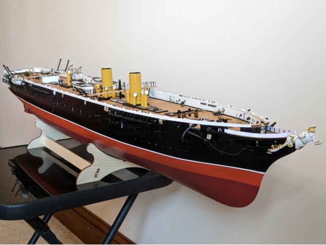
The stand can now be cleaned up and painted, then carefully secured to the hull. The final task is to carefully examine every detail of the vessel. Inevitably there will be odd loose ends of rigging to be cut or secured. Brass wire fittings to be painted. The odd deck fitting may have come loose and need to be re-secured. In hindsight I would leave the fitting of the lower deck gunport doors until all else is complete. I fitted them much earlier in the build, and spent the next four months knocking them off; they are very vulnerable! One or two disappeared into the hull, lost forever, necessitating the making, painting and fitting of new ones.
Finally, the hull is secured onto the stand and all is complete. And does she look impressive! This is a large model, constructed from a large kit. The project has taken me nine months to complete, by far my biggest and longest project, and I enjoyed the process immensely. The kit was well presented and provided, and the project definitely for the more experienced modeller.
So, what next for the breakfast-bar shipyard? Watch this space!
Model of HMS "Warrior" - 3


Full Gallery
Click an image to see the full size images.
HMS Warrior kit 
HMS Warrior, Portsmouth 

Model of HMS "Warrior" - 1 

Model of HMS "Warrior" - 3 Model of HMS "Warrior" - 2
